Transponder is intended for the use in the
Cubesat type satellite Bricsat as dual board with
connection to other parts of the satellite. Single channel 3kHz
bandwidth is intended for multiple PSK31 transmissions through transponder with
FM signal downlink. Additionally the
beacon is implemented to identify the channel and to give info about transponder
health.
Mission status
Transponder
is onboard the cubesat BRICsat planned for launch on
AFSPC-5 mission on May 20 2015 from Cape Canaveral.
We will be
very grateful for any info about transponder downlink status around the world.
You can send us decoded telemetry frames on our email
psktransponder@centrum.cz. Please specify time of the reception and position of
station. Additional info would be welcomed. If you save the demodulated audio,
send us the wav files, the email should handle great amount of data. If you use
the SDR radio for reception, nondemodulated IF with
bandwidth minimum 40kHz accommodating thermal drift
and doppler would be welcomed.
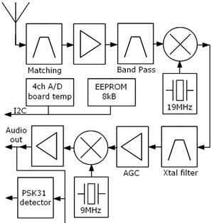
Fig.1
Receiver block diagram
A block
diagram of the HF receiver part of the band monitor is depicted in Fig. 1.
We use a double conversion super heterodyne, proven in PCSAT2 receiver, with
several modifications - especially the BPSK31 signal sensing circuits.
The
receiver includes low noise preamplifier with BFS17 in order to compensate
electrically short receive antenna, which must be shorter to fit in the small
Cubesat. The LNA is followed by high quality LC filter for the out of band
signal suppression. Then there is first mixer NE602 to intermediate frequency
followed by a crystal filter, which defines actual bandwidth 3 kHz of monitored
HF band. The intermediate frequency amplifier A281D with the gain setting
ability for automatic gain control then amplifies the received signal and it is
followed by the last mixer NE602, which converts the signals to the audio band.
The baseband
signal is then splitted into four ways. The first
signal is rectified and the obtained DC voltage controls the gain of the
intermediate amplifier via the MC34072 amplifier.
The second
signal is rectified to get 31.25 Hz frequency from the received signals. Then
it is amplified and filtered by MC34072. This spectral component is a part of
the BPSK31 signal modulation which is most frequently used digital mode in the
monitored radio-amateur band. After passing through the narrow bandwidth tone
decoder NE567, binary signal carrying information about presence of BPSK31
modulation is obtained. It is monitored by a control microprocessor of
transmitter in order to recognize useful signal and switch the power amplifier
on.
The third
signal is also amplified by MC34072 which also works as amplitude limiter and
through preemphasis filter it is connected to the
transmitter modulation input to modulate the UHF carrier.
The
receiver board also holds the digital chips 24LC64 and AD7417, the former to
store whole orbit data and the latter for the battery voltage measurement -
single cell should be measured. Other three channels are at disposition for
monitoring of other parts of satellite. The AD chip also monitors the
temperature of RX board. Both are connected to I2C bus.
The board
is 0.8mm FR4 material with the size 63.4 mm x 63.4 mm.
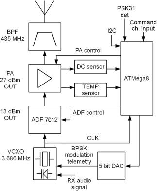
Fig.2
Transmitter block diagram
The
transmitter produces FM modulated signal in UHF frequency band. Output RF power
of the transmitter is 24 dBm at 435 MHz. A BPSK
modulator with data rate 31.25 bit/s on a sub carrier with frequency 375 Hz is
implemented in order to transmit telemetry data from built-in sensors. Block
diagram of the transmitter is depicted in Fig. 2.
The core of
the transmitter is integrated transceiver IC ADF7012 produced by Analog
Devices. This solution with minimum number of external components results in
minimal dimensions of the PCB board. The ATMega8 3.686MHz quartz oscillator is
directly modulated by a varicap in order to achieve linear
FM modulation. Output power is amplified by one-stage PA with a Mitsubishi RD02MUS1B
MOSFET transistor. Finally, the signal is filtered by a band pass. On the board
are implemented sensors which measure drain voltage, current (MAX4372) and
temperature (AD7415) of the PA transistor. If the maximum allowed temperature
is reached, the controller immediately shut the PA down to preserve it from
overheating. All sensors and the transceiver IC are controlled by microcontroller
ATmega8. The microcontroller also drives a 5-bit parallel DA converter, which
provides BPSK modulation of the telemetry data.
The board
is 0.8mm FR4 material with the size 63.4 mm x 63.4 mm.
Both boards
are interconnected with double row 20pin connector and mechanically mounted
with four M3 spacers. The height of the spacers should be approximately 6.5mm
to ensure reliable connection in the connector.
Connectors
should be connected / disconnected with the special attention to the board
flexing to avoid parts stressing.
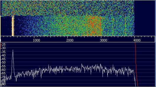
Fig.3
Output demodulated spectrum with beacon
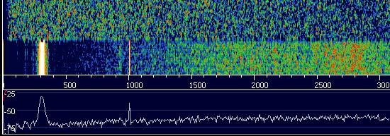
Fig.4
Output demodulated signal with beacon and CW signal in transponder
Input
frequency:
Figure
above shows result of CW signal injection into transponder with frequency 28.TBA
MHz. Signal is at the 1000Hz mark. From that we conclude the input frequency:
F LO = 28.120030 MHz
And resulting operating passband range:
28.120530MHz - 28.122930MHz
Output center
frequency:
435.351
MHz with FM modulation
Beacon specification
The beacon
is implemented as added BPSK31 signal into linear audio signal from receiver.
The BPSK31 signal is upconverted to 371.5Hz
subcarrier frequency to position it in the spectrum below the receiver passband.
aaaaaaa b ccddeeffgghhiijjkkllmm
Where:
|
symbol
|
width
|
description
|
unit
|
|
aaaaaaa
|
5
|
Call sign assigned
by IARU
|
-
|
|
b
|
1
|
Mode of operation
|
-
|
|
cc
|
2
|
Frame number
|
-
|
|
dd
|
2
|
PSK sensing
|
-
|
|
ee
|
2
|
RX AGC
|
-
|
|
ff
|
2
|
Battery voltage across
all 2 cells
|
10mV
|
|
gg
|
2
|
Battery voltage across
lower cell
|
10mV
|
|
hh
|
2
|
voltage1 TBA
|
10mV
|
|
ii
|
2
|
voltage2 TBA
|
10mV
|
|
jj
|
2
|
voltage3 TBA
|
10mV
|
|
kk
|
2
|
Transmitter
current consumption
|
mA
|
|
ll
|
2
|
Receiver
temperature +99
|
°C
|
|
mm
|
2
|
Power amplifier
temperature +99
|
°C
|
aaaaaaa identification of the beacon (callsign W3ADO-6)
b A, B, C (A - transmitter
always on, B - transmitter turns on, if BPSK31 signal is present, C beacon
only, callsign only in D mode)
cc number
of frame (0 ... 804)
dd percentage
of BPSK31 detection (0 ... 99%)
ee percentage
of AGC operation (0 ... 99%)
ff supply voltage (10 mVolts)
gg voltage
across lower cell.(10 mVolts)
hh voltage1
(10 mVolts)
ii voltage2 (10 mVolts)
jj voltage3
(10 mVolts)
kk power
amplifier current (mAmps)
ll temperature
of receiver +99 (-98 ...156 deg C)
mm temperature of PA transistor +99
((-98 ...156 deg C)
Full frames are transmitted in a numeral system
with base 32. All 32 values are represented by symbols "a" for 0 to
"z" for 25 and "A" for 26 to "F" for 31. Such
representation allows to encode numeral values in
range 0 to 1023, with use of two symbols only.
The telemetry values for dd and ee are averaged throughout the
previous 20s interval, the other values for voltage, current and temperature
are measured in the time when transmitter is switched on and transmitting the
synchronization, then the callsign transmission
follows.
The ee AGC measured voltage is highly nonlinearly dependent on
the input signal, morover the limiting values of
measurement vary with temperature of the chip and its supply voltage.
Indicative only conversion equation was computed as from 50Ohm generator to
input of receiver
Pin = 0.370xee-137.4 [dBm, %]
The temperatures are transmitted with 99 added to eliminate the sign
problems. So
Trx=ll-99
[°C]
And the same applies for PA temperature
Tpa=mm-99 [°C]
Example:
W3ADO-6 A cAagbexgaaaaaaaafdeadF
converted
to base 10:
W3ADO-6 A 90 6
36 742 0
0 0 0 163 128
127
It means mode A active, frame number 90, BPSK31 06 %, AGC acting 36%,
supply voltage 7.42V, voltage across lower cell 0V (actually unconnected),
voltage1 to voltage3 0V, PA current 163mA, temperature of the receiver +29°C
and temperature of PA transistor of +28°C.
Mode A means transmitter is always on, receiver is always on.
Mode B means,
that receiver is always on and transmitter is switched on in the 20s slots
depending on the PSK31 activity in the pass band of receiver. When no activity
occurs, transmitter is switched on to transmit beacon telemetry every 120s.
Fig.5a
Timing of the mode B beacon
As can be
seen in Fig. 5a, the beacon is transmitted in approx. 10s and next transmittion is starting every 120s at maximum, or sooner,
when the PSK31 signal is detected in the passband.
Mode C
Mode C
means, that receiver is always on, however the transmitter is swichted on only every 180s to transmit beacon telemetry.
Fig.5b
Timing of the mode C beacon
As can be
seen in Fig. 5b, the beacon is transmitted in approx. 10s and next transmittion is starting every 180s
Mode D
Mode D
means, that receiver is always on, however the
transmitter is swichted on only every 180s to
transmit callsign only, without telemetry.
Fig.5c
Timing of the mode D beacon
As can be
seen in Fig. 5c, the beacon is transmitted in approx. 4s and next transmittion is starting every 180s
The
transponder includes the EEPROM memory able to store some 804 lines of telemetry.
In the every time, telemetry is transmitted over the air,
it is also stored into memory. That way it is possible to download the history
of the transmissions, only mode letter is not stored, but it can be
reconstructed from the step of the frame number. The minimum history time
stored in memory is in mode A 20s frame length*804 which results in approx.
4.45hour. In the case of mode B maximum time is 120s repetition*804 means
maximum of 26.7hour. In the case of modes C and D. The
time would be exactly 180s*804, that is 40.2 hour
history. The data can be transmitted in 64 or 125BPSK.
Example:
When proper
command is transmitted, transponder acknowledges with cmd
879 700 70 br1 which means WOD data transmission of time and supply voltage was
requested, and it will be transmitted by 64BPSK. Then it starts to send data.
Received
data:
da
xgnonononono
cA xgigioioioio
bw
wEioioioioio
as wEioio em zrnono
Data are
first sent in the full frame with spaces, and then there are 5 sets of compressed
values in one line. The compressed frames are obtained as a difference between
last and previous value of each telemetry channel plus 14. If the result lies
in 0 to 31 range, the value is transmitted as one symbol, otherwise the value
is sent as its full representation preceded by space.
Transmission goes from recent time to deeper history reading full memory.
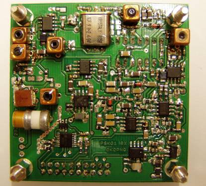
Fig. 6
Top side of the RX board
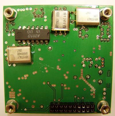
Fig. 7
Bottom side of the RX board
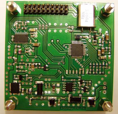
Fig. 8
Top side of the TX board
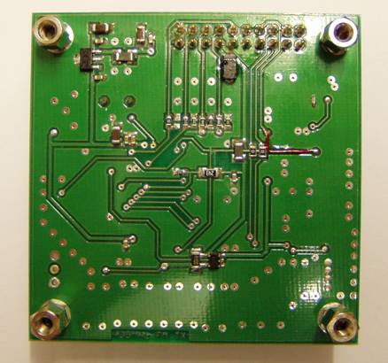
Fig. 9
Bottom side of the TX board
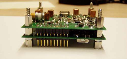
Fig. 10
Side view of the board, RX up
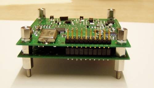
Fig. 11
Side view of the board, TX side up