10.4 Quarter wavelength monopole antenna − ground-plane antennaBasic theoryThe quarter wave antenna is a single element antenna fed at one end that behaves as a dipole antenna. It is formed by a conductor in length λ/4. It is fed in the lower end, which is near a conductive surface
which works as a reflector. The current in the reflected image has the same direction and phase that the current in the real antenna. The set quarter-wave plus image forms a half-wave dipole that radiates only in the upper half of space.
In this upper side of space the emitted field has the same amplitude of the field radiated by a half-wave dipole fed with the same current. Therefore, the total emitted power is one-half the
emitted power of a half-wave dipole fed with the same current. As the current is the same, the radiation resistance (real part of series impedance) will be one-half of the series impedance of a half-wave dipole. As the reactive part is
also divided by 2, the impedance of a quarter wave antenna is 36 + j21 . The gain is the same as that for a half-wave dipole (λ/2) that is 2.14 dBi.
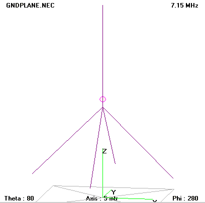 |
| Fig. 10.4A.1 | Wire model of ground plane antenna |
|
Far from the antenna and near the ground, electromagnetic fields and radiation patterns are the same as for a half-wave dipole. The impedance is not the same a with a good conductor ground plane.
Conductivity of earth surface can be improved with an expensive copper wire mesh.
When ground is not available, as in a vehicle, other metallic surfaces can serve a ground plane, for example the roof of the vehicle. In other situations, radial wires placed at the foot of the
quarter-wave wire can simulate a ground plane.
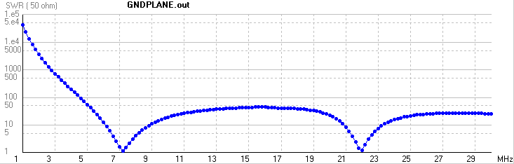 |
| Fig. 10.4A.2 | Frequency response of standing wave ratio of ground plane antenna (the length l = 10.257 m) |
|
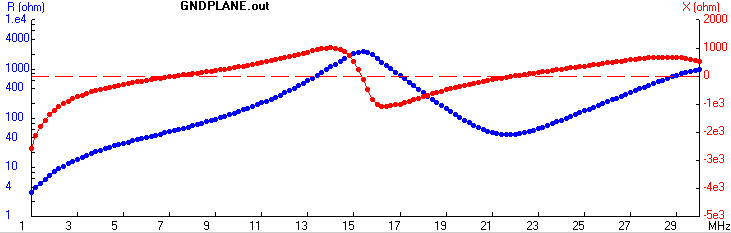 |
| Fig. 10.4A.3 | Frequency response of input impedance of the ground plane antenna (the length l = 10.257 m) |
|
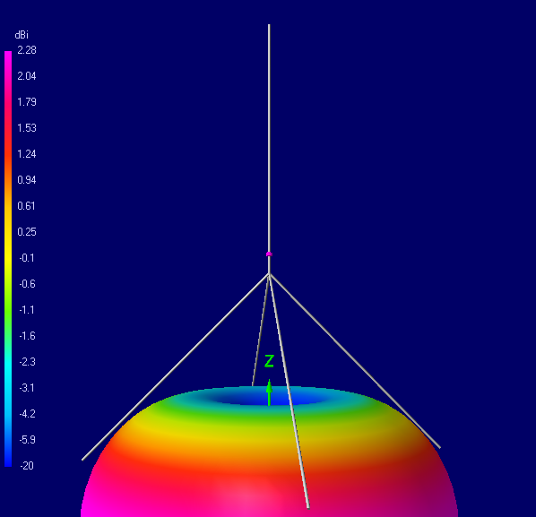 |
| Fig. 10.4A.4 | Radiation pattern of ground plane antenna at 7.1 MHz (the length l = 10.257 m) |
|
|