10.6 Inverted VeeBasic theoryAn inverted Vee antenna is a modified dipole antenna supported in the center with the ends lower than the center. Inverted Vee antennas are commonly used by many amateur radio stations, and aboard
sailing vessels requiring better HF performance than available with a short whip antenna.
 |
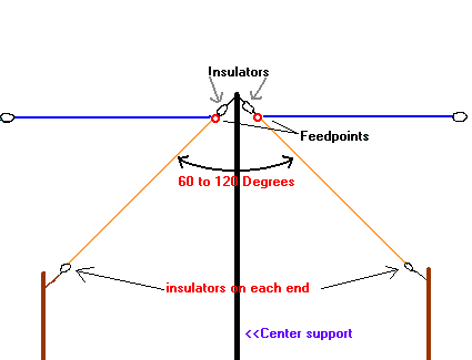
| Fig. 10.6A.1 | Basic structure of In-Vee antenna |
|
Typically, the inverted Vee antenna requires only a single, tall support at the center (often a convenient tree limb), and the ends can be insulated and secured to anchors at or near ground level. This
simplified arrangement has several advantages, including a shorter ground distance between the ends. For example, a dipole antenna for the 80 meter band requires a ground length of about 43 m from end to end. An inverted Vee with 12 m apex elevation requires only 35 m. For radio amateurs living on small parcels of property, such
savings can make it possible to use the lower frequency amateur bands.
In theory, the gain of an inverted Vee is similar to that of a dipole at the same elevation because most of the radiation is from the high-current portion of the antenna, which is near the center.
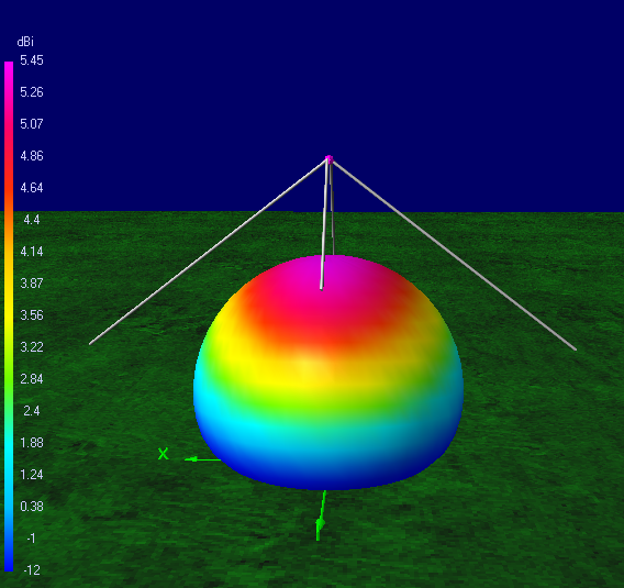
Since the center of both antennas is the same height, there is little difference in performance. Antenna modeling software predicts maximum gain of 2.15 dBi for the dipole and 1.9 dBi for the inverted Vee.
However, in practice, ground proximity and ground conductivity as well as end effects reduce the efficiency of the inverted Vee considerably compared to the dipole. In the 40-foot example above,
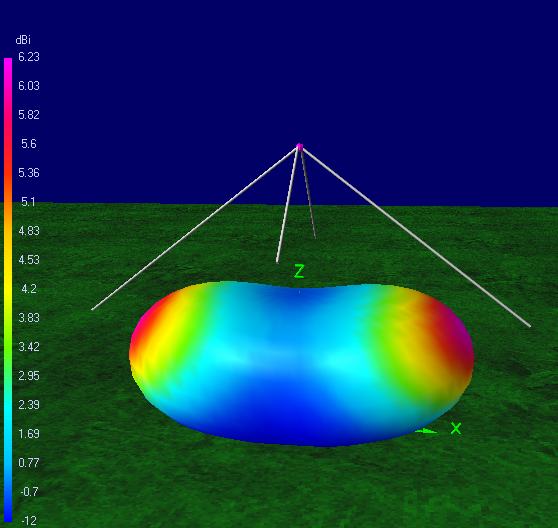
considering a useful take-off angle of 40 degrees above the horizon, the inverted Vee produces a maximum gain of 1 dBi in a circular pattern, whereas the dipole produces an oval pattern ranging from 6 dBi toward the
sides down to 1.2 dBi toward the ends.
 |
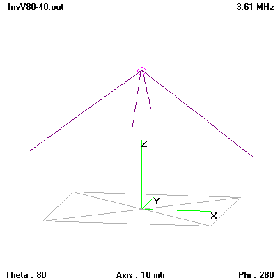
| Fig. 10.6A.2 | Wire model of In-Vee antenna |
|
 |
| Fig. 10.6A.3 | Frequency response of standing wave ratio of In-Vee antenna (the length l80 = 15.9 m, the length l40 = 7.74 m) |
|
 |
| Fig. 10.6A.4 | Frequency response of input impedance of In-Vee antenna (the length l80 = 15.9 m, the length l40 = 7.74 m) |
|
 |  |
| Fig. 10.6A.5 | Radiation pattern of In-Vee antenna at 3.5 MHz and 7.05 MHz (the length l80 = 15.9 m, the length l40 = 7.74 m) |
|
|


