10.7 Yagi antennaBasic theory
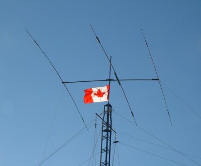
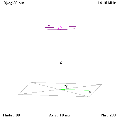
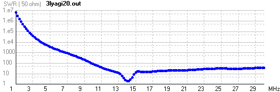
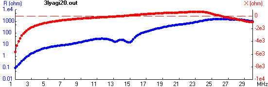
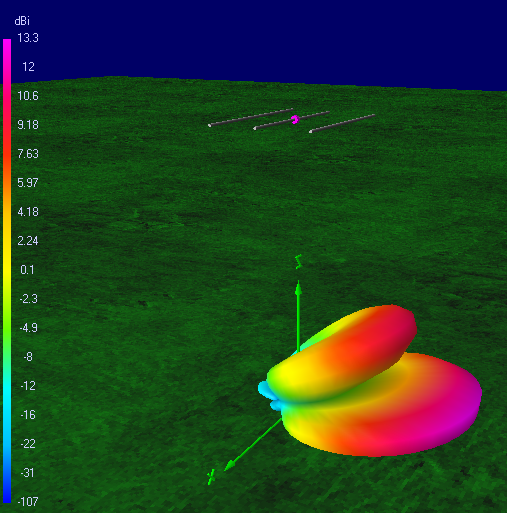
A Yagi-Uda Antenna, commonly known simply as a Yagi antenna or Yagi, is a directional antenna system consisting of an array of a dipole and additional closely coupled parasitic elements (usually a reflector and one or more directors). The dipole in the array is driven, and another element, typically 5% longer, effectively operates as a reflector. Other parasitic elements shorter than the dipole may be added in front of the dipole and are referred to as directors. This arrangement gives the antenna increased directionality compared to a single dipole. Directional antennas, such as the Yagi-Uda, are also commonly referred to as beam antennas [46] or high-gain antennas (particularly for transmitting). Many common television antennas are Yagi antennas with added corner reflectors. Yagi-Uda antennas are directional along the axis perpendicular to the dipole in the plane of the elements, from the reflector through the driven element and out via the director(s). Typically, all elements are arranged at approximately a one-quarter-wavelength mutual spacing. All elements usually lie in the same plane, supported on a single boom or crossbar; however, they do not have to assume this coplanar arrangement. For example, some commercially available Yagi-Uda antennas for television reception have several reflectors arranged to form a corner reflector behind the dipole. The bandwidth of a Yagi-Uda antenna, which is usually defined as the frequency range for which the antenna provides a good match to the transmission line to which it is attached, is determined by the length, diameter and spacing of the elements. For most designs, bandwidth is low, typically only a few percent of the design frequency. Yagi-Uda antennas can be designed to operate on multiple bands. Such designs are more complicated, using pairs of resonant parallel coil and capacitor combinations (called a "trap" or LC) in the elements. The trap serves to isolate the outer portion of an element from the inner portion at the trap design frequency. In practice, the higher frequency traps are located closest to the boom of the antenna. Typically, a triband beam will have two pairs of traps per element. For example, a triband design covering the 10, 15 and 20 meter bands would have traps for the 10 and 15 meter bands. The use of traps is not without cost, as they reduce the bandwidth of the antenna on each band and reduce its overall efficiency. There are no simple formulas for designing Yagi-Uda antennas due to the non-linear relationships between physical parameters such as element length, diameter and position and electrical characteristics such as input impedance and gain. Consequently, designs are found experimentally either through direct measurement or computer simulation, or by modifying existing designs. Yagi-Uda antennas are widely used by amateur radio operators worldwide for communication on frequencies from shortwave, through VHF/UHF, and into microwave bands. Hams often homebrew this type of antenna, and have provided many technical papers and software to the engineering community.
|