10.8 Logarithmic-periodical antenna (LPA)Basic theory
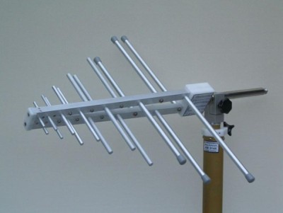 |
| Fig. 10.8A.1 | Practical implementation of LPA antenna |
|
In telecommunication, a log-periodic antenna (LP, also known as a log-periodic array) is a broadband, multielement, unidirectional, narrow-beam antenna that has impedance and radiation
characteristics that are regularly repetitive as a logarithmic function of the excitation frequency. The individual components are often dipoles, as in a log-periodic dipole array (LPDA). Log-periodic antennas are designed to be
self-similar and are thus also fractal antenna arrays.
It is normal to drive alternating elements with 180° (π radians) of phase shift from one another. This is normally done by connecting individual elements to alternating wires of a balanced transmission line.
The length and spacing of the elements of a log-periodic antenna increase logarithmically from one end to the other. A plot of the input impedance as a function of logarithm of the excitation frequency shows a periodic variation.
This antenna design is used where a wide range of frequencies is needed while still having moderate gain and directionality. It is sometimes used for a (VHF/UHF) television antenna.
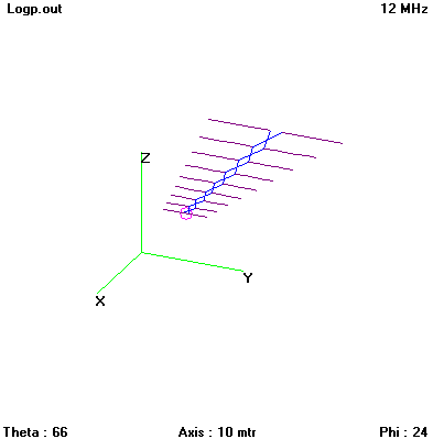 |
| Fig. 10.8A.2 | Wire model of LPA antenna |
|
 |
| Fig. 10.8A.3 | Frequency response of standing wave ratio of LPA antenna (length d1 = 2.142 m, d2 = 2.463 m, spacing s1 = 1.143 m, d3 = 2.833 m, s2 = 2.803 m, d4 = 3.255 m, s3 = 4.713 m, d5 = 3.741 m, s4 = 6.903 m, d6 = 4.299 m, s5 = 9.833 m, d7 = 4.941 m, s6 = 12.313 m, d8 = 5.682 m, s7 = 15.633 m, d9 = 6.531 m, s8 = 19.463 m) |
|
 |
| Fig. 10.8A.4 | Frequency response of input impedance of LPA antenna (length d1 = 2.142 m, d2 = 2.463 m, spacing s1 = 1.143 m, d3 = 2.833 m, s2 = 2.803 m, d4 = 3.255 m, s3 = 4.713 m, d5 = 3.741 m, s4 = 6.903 m, d6 = 4.299 m, s5 = 9.833 m, d7 = 4.941 m, s6 = 12.313 m, d8 = 5.682 m, s7 = 15.633 m, d9 = 6.531 m, s8 = 19.463 m) |
|
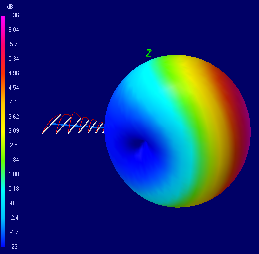 |
| Fig. 10.8A.5 | Radiation pattern of LPA antenna at 14 MHz (length d1 = 2.142 m, d2 = 2.463 m, spacing s1 = 1.143 m, d3 = 2.833 m, s2 = 2.803 m, d4 = 3.255 m, s3 = 4.713 m, d5 = 3.741 m, s4 = 6.903 m, d6 = 4.299 m, s5 = 9.833 m, d7 = 4.941 m, s6 = 12.313 m, d8 = 5.682 m, s7 = 15.633 m, d9 = 6.531 m, s8 = 19.463 m) |
|
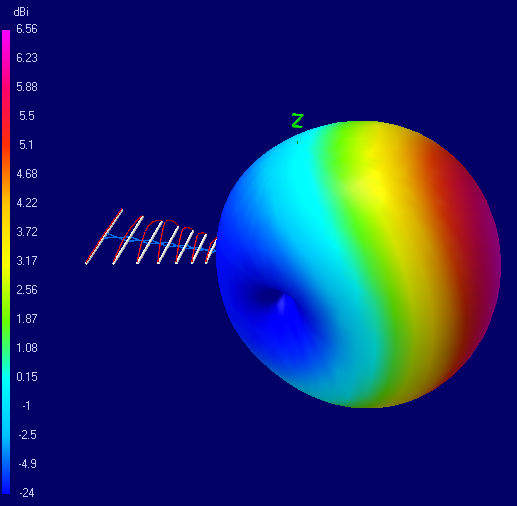 |
| Fig. 10.8A.6 | Radiation pattern of LPA antenna at 21 MHz (length d1 = 2.142 m, d2 = 2.463 m, spacing s1 = 1.143 m, d3 = 2.833 m, s2 = 2.803 m, d4 = 3.255 m, s3 = 4.713 m, d5 = 3.741 m, s4 = 6.903 m, d6 = 4.299 m, s5 = 9.833 m, d7 = 4.941 m, s6 = 12.313 m, d8 = 5.682 m, s7 = 15.633 m, d9 = 6.531 m, s8 = 19.463 m) |
|
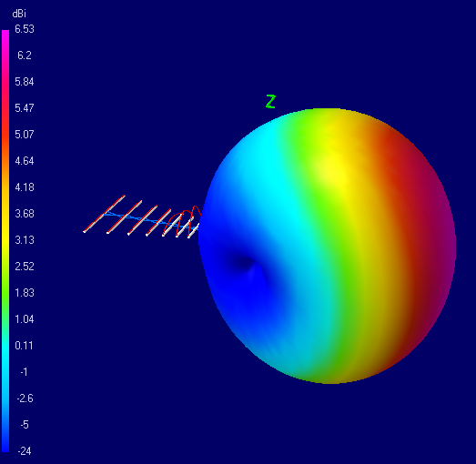 |
| Fig. 10.8A.7 | Radiation pattern of LPA antenna at 28 MHz (length d1 = 2.142 m, d2 = 2.463 m, spacing s1 = 1.143 m, d3 = 2.833 m, s2 = 2.803 m, d4 = 3.255 m, s3 = 4.713 m, d5 = 3.741 m, s4 = 6.903 m, d6 = 4.299 m, s5 = 9.833 m, d7 = 4.941 m, s6 = 12.313 m, d8 = 5.682 m, s7 = 15.633 m, d9 = 6.531 m, s8 = 19.463 m) |
|
|


