2.2 General Theory of diffractionAdvanced theoryNow, we are going to become familiar with the theory, which enables us to solve diffraction tasks on objects of more general shape in an analytical way. As demonstrated, generality of the solution is related to the physical approach only. From the formal (mathematical) point of view, the described approach can be practically applied to computing the diffraction on objects of a geometrically simple shape.
As described in the layer A, the physical principle is as follows. In the surrounding of the object, a known primary wave, which illuminates the object, exists. As an effect of illumination (i.e., due to the induced currents), the object becomes the source of own, secondary wave, which propagates from the object in all the directions. The total intensity in the surrounding of the object is given by the summation of field intensities of the primary wave and the secondary one. Since the intensity of the primary wave is known, we have to compute the secondary-wave intensity only. The following two conditions can help us for that:
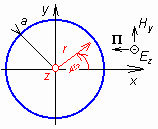
Up to now, everything seems being clear. Unfortunately, factual computations bring difficulties. Therefore, we describe the solution of the plane wave diffraction on an infinitely long perfectly conducting circular cylinder without significant mathematical skips here. The cross section of the cylinder is depicted in fig. 2.2B.1. The cylinder axis is identical with the z axis of the Cartesian coordinate system, and the radius of the cylinder is a. The cylinder is illuminated by the plane wave propagating in the direction -x and the electric-intensity vector E has got a single component Ez i.e. is parallel with respect to the cylinder surface). Since in all cuts lying in parallel with the plane xy the situation is the same, the task can be solved in two dimensions. Due to the axial symmetry, the task is solved in the cylindrical coordinate system. In the planar cut, the solution is found in polar coordinates r, φ (see fig. 2.2B.1). Obviously, x = r cos(φ). Considering the above description, filed intensity of the primary wave is
Field intensity of the secondary wave has to meet the wave equation
Rewriting operator ∇2 for the cylindrical coordinate system [1] and substituting d/dz = 0, we obtain
The above equation is solved by the method of variables separation. We assume Ez = R(r) Φ(φ) and substitute to (2.2B.3). Deriving by φ is R constant and vice versa. Then, the equation is divided by RΦ and the term containing φ and Φ is simply separated. The rest of terms contain r and R only then. The equation is separated. If the equation should be valid for any combination of variables r and φ, each of both separated parts of the equation has to be constant. The term containing φ and Φ only is put being equal to –m2, where m is so called separation constant. That way, the following equation is obtained:
Eqn. (2.2B.4) is the second-order differential equation with constant coefficients (m). Solving it via characteristic equation, the result can be expressed by exponential functions or goniometric ones. Since the result, i.e. the function Φ(φ), describes the field-intensity dependency on the coordinate φ, i.e. around the cylinder axis, and since no traveling wave is expected in this direction, we choose goniometric functions:
A and B, or C and φ0 denote integration constants. Here, we prefer the last form of the solution, where the constant φ0 depends only on the direction from which the angle φ is measured. Thanks to the axial symmetry, the direction φ = 0 can be chosen arbitrarily, and therefore, we put φ0 = 0. The final relation is formally simplified that way. Considering eqn. (2.2B.5), another important conclusion can be done. Changing the angle φ for 2π, we reach the same point of the space, i.e. we come back to the same field intensity, and consequently to the same functional value of Φ. This is conditioned by the requirement that the separation constant m is integer number. Now, turn our attention to the second part of the eqn. (2.2B.3), which contains variables r and R. This second part is of the form
Substituting ρ = kr and performing simple rearrangements, we get Bessel equation:
Since the constant m is integer number, the solution of Bessel equation is a linear combination of Bessel and Neumann functions or linear combination of Hankel functions of the first kind or of the second kind. Since the function R describes field-intensity dependency on the radial coordinate r (the direction outwards the cylinder), and in that direction the wave propagates, we choose Hankel functions. Since Hankel functions of the first kind describe the wave from the infinity to its source and Hankel function of the second kind describes the wave propagating outwards the source, we choose the second-kind function only. Combining the solution of (2.2B.4) and (2.2B.7), we yield the general integral of the equation (2.2B.3):
Eqn. (2.2B.3) is fulfilled by the solution of (2.2B.8) for each integer m. Since the right value of m unknown this time, we have to admit all the possible values of the separation constant m and even the arbitrary linear combination of those solutions. The final result of solving (2.2B.3) can be expressed in the form of an infinite series
The result (2.2B.9) can be understood as a set of the infinite number of waves propagating outwards the cylinder, which mutually interfere into the secondary wave. Each summand of the series (2.2B.9) represents one of these partial waves. These waves differ in their amplitudes (unknown coefficient Am), in their dependency on the radial distance r (the coefficient Hm(2)(kr) depends on m) and also in their dependency on φ, i.e. on the direction outwards the cylinder. The wave with m = 0 propagates in all the directions with the same amplitude cos(mφ) = cos(0) = 1 = const., the wave with m = 1 exhibits eight-like directivity pattern (maximum for j = 0, π; zero amplitude for φ = ±π/2), etc. At this moment, the solution seems to become complicated. But, thanks to the infinite series (2.2B.9), the solution can be successfully finished. Properly choosing coefficients Am we can enforce the series (2.2B.9) to meet in its whole those boundary conditions, which have to be met on the surface of the object (the situation is conformable to Fourier series: a proper choice of Fourier coefficients enables us to express an arbitrary time course of the signal). If perfectly conducting and infinitely long cylinder is assumed, than the boundary condition is formulated in a simple way: the tangential component of the total-field intensity has to be zero on the surface. Since our wave consists of the component Ez only, which is parallel to the surface, we get
Substituting from (2.2B.1) and (2.2B.9), we get
From the above equation, unknown coefficients Am have to be computed. Unfortunately, a single equation of an infinite number of coefficients is at our disposal. In similar situations, the method of inexplicit coefficients ([1], [4]) can help us. This method requires all the addends (both in our case) in eqn. (2.2B.11) being expressed by a series of the same type (in our case, by a series containing terms cos(mφ). If this requirement is satisfied then m = 0, 1, 2, ... ∞ are sequentially substituted to the equation, and that way, the single equation comes to the set of the infinite number of equations for coefficients Am. Fortunately, we know that
which enables us to expand the primary wave to the series consisting of term of the type cos(mφ). The series is substituted to (2.2B.11), and coefficients at cos(φ), cos(2φ), cos(3φ),... are sequentially compared. That way, following relations are obtained:
and consequently
That way, the analytical solution of our task is finished. First, coefficients Am are evaluated, and then, the secondary wave is given by the series (2.2B.9). The total-field intensity in the cylinder surrounding is obtained by adding field intensities of the secondary wave (2.2B.9) and the primary one (2.2B.1). Finally, let us remind conditions of the successful operation of the method. First, the object shape has to be simple; its surface has to be identical with a plane in such coordinate system, where the wave equation (2.2B.2) can be solved. Second, the primary wave has to be expanded into the series of the same type, which is given by the solution of the wave equation. Finally, the secondary-wave series has to exhibit the satisfactory convergence. The convergence is rather problematic in situations, when object dimensions are several-orders larger than the wavelength. E.g., if computing the diffraction of very short waves on the surface of the globe, then the satisfactorily accurate expression of the secondary wave requires addition of tens and hundreds millions of addends in some regions. Today, the solution of the diffraction task is known for various simple objects: sphere, cylinder (spherical elliptical, parabolic) and for general ellipsoid; the proper choice of the half-axis length enables to approximate technically useful shapes. For a = b = c the ellipsoid becomes a sphere. For a = b << c the ellipsoid approximates a cylindrical conductor of a finite length. For a = b >> c the ellipsoid approaches a circular slab. The structure of the wave was briefly commented in the layer A. In the surrounding of the cylinder, both the traveling wave and the standing one exist. The standing wave is created by the interference of the primary wave and the secondary one. Since both the waves are of the different propagation direction and since event the phase velocities of both the waves are different, the wavelengths of the standing wave are in different directions different too. Surprisingly, the secondary wave exhibits the highest intensity in the direction behind the cylinder. If the radius of the cylinder is smaller than approx. 1/10 of the wavelength, the the influence of the cylinder to the primary wave is negligible. In detail, the structure of waves can be studied using computer programs (see the layer C). The first program displays field intensity of the secondary wave and of the total one in polar coordinates in the form of directivity patterns. Field intensities in various directions in a constant distance from the cylinder axis can be observed. The second program shows the distribution of field intensities along radial lines in different directions. A more detailed description is given in the layer C. Finally, a brief note on the solution of the diffraction task in the situation, when the conductivity of the cylinder is not infinite or if a dielectric cylinder is analyzed. In that case, the wave equation (2.2B.2) has to be solved even inside the cylinder. There, waves do not propagate and the standing wave appears there. Therefore, we do not use Hankel functions the solution of he wave equation, but Bessel and Neumann functions are exploited. Since for r = 0 (on the cylinder axis) the value of Neumann function approaches infinity whereas the field intensity has to be finite, we have to eliminate this function. In analogy to (2.2B.9), we can write for the region inside the cylinder:
The coefficients can be determined using the boundary condition
Even here all the intensities have to be expressed in the form of series of the same type, and the method of inexplicit coefficients [4] has to be applied. Since two infinite sets of unknown coefficients (Am, Bm) appear here, the only condition (2.2B.16) is insufficient. The solution has to be repeated even for magnetic field including the proper boundary condition. |