2.5 Wave propagation in layered mediaBasic theoryIn several technical equipments, media consisting of several layers, which differ in their permittivity, permeability and thickness, are used. Hence, the layered medium is composed of a certain number of plan-parallel dielectric layers (or slabs). The layered media (or structures) enable to build reflection-free walls. Those layers absorb the wave incident to a surface, which is covered by several dielectric layers of properly chosen parameters, without exhibiting significant reflections (reflection coefficient approaches zero). Applications can be found in anechoic chambers or at military equipment, e.g. The layered structures can provide a reflection-free transition of a wave from one media to another one (from air to water, e.g.) in the sense of impedance matching. As a matching circuitry, a set of several dielectric layers, inserted between the media, can be considered. To this set of applications, dielectric radomes of antennas and HF devices belong. The radome has to preserve the device mechanically, but it must not influence the propagation of the electromagnetic wave. In the following, we consider a normal incidence of waves with respect to the boundary among layers. The explanation is divided into two parts. In the first part (layer A), phenomena inside the layered medium are observed (changes of intensities on boundaries and inside layers). In the second part (layer B), the phenomena are investigated from the global point of view and parameters of the medium are computed in its whole. In the layered medium, multiple reflections and transmissions of waves on single boundaries can be observed. Therefore, important terms related to the reflection and to the transmission are reminded.
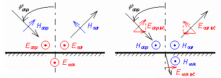
Plane of boundary is a plane separating two media. Plane of incidence is perpendicular to the plane of boundary and is parallel to the direction of the wave propagation. If the wave is of the perpendicular (horizontal) polarization, the vector E is perpendicular to the plane of incidence. If the wave is of the parallel (vertical) polarization, the vector E is parallel to the plane of incidence. Orientation of vectors for both the polarizations depicted in fig. 2.5A.1. Plane of boundary is perpendicular to the plane of the screen. Plane of incidence is identical with the plane of the screen. Each point on the boundary has to be considered as two points in an infinitely short distance. The first point is in the first medium, the second point belongs to the second medium. In each point in the plane of boundary, two various field intensities are therefore considered: E1, E2 and H1, H2 - each one in another medium. However, every time the tangential components of electric field intensity and the normal components of electric displacement density have to equal:
Similar relations are valid even for vector H if no currents flow on the boundary. From the basic boundary condition (2.5A.1a), important relations among intensities, which are depicted in fig. 2.5A.1, can be derived: For perpendicular polarization:
For parallel one:
The ρ⊥ and ρ| are reflection coefficients for the perpendicular polarization and the parallel one. Generally,
As already mentioned, we are going to deal with normal wave incidence to the boundary only. Reflection coefficients depend then on wave impedances Z01 and Z02 of both media only
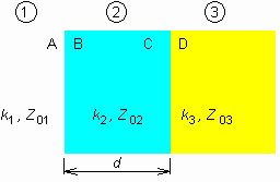
Considering the normal incidence, the difference between polarizations disappears. Reflection coefficients differ in the sign, but the positive direction of Eodr differs in the orientation on the other hand (see fig. 2.5A.1), and therefore, the result for both polarizations is the same. During the wave propagation in a layered medium, the same phenomenon repeats many times: the wave transmits the boundary and then, it freely propagates through the dielectric layer towards the next boundary. From the physical and the mathematical point of view, only two phenomena are needed to be managed: the boundary transition and the layer propagation. The explanation will be given for the situation, which is depicted in fig. 2.5A.2. Here, three media 1 to 3 are shown. Their wave impedances Z0i = (μi / εi)1/2 and wave numbers ki = ω (μi εi)1/2 are indexed the same way. The media are separated by two boundaries, which consist of two planes (A, B; C, D): one of them is expected to be in the first medium and the second of them in the second medium. The wave propagates from left, transits the boundary perpendicularly, and is perpendicularly polarized; vectors E and H are tangential to the boundary. In the general case, both the forward wave and the backward one propagate in all the media, and therefore, the standing wave appears there. Intensities (E and H) of the forward wave are denoted by the index p, intensities of the backward wave by the index z. The other index specifies the position where the intensity is measured. Total intensities do not contain any index (neither p nor z)
(minus in (2.5A.4b) corresponds with fig. 2.5A.1). Considering the above-introduced notation, EB is total intensity on the boundary 1-2 in the medium 2, EA(z) is intensity of reflected wave on the same boundary but in the medium 1. Analysis of the wave propagation in the layered medium can be performed using two approaches. The difference between approaches is formal, but in given situations, it can influence the way of computing. No matter which approach is used, the analysis is done from the end of the medium to its beginning (in the contra-direction of the forward-wave propagation). The first approach is based on the boundary condition (2.5A.1). Total intensities on both sides of the boundary have to be the same. E.g., for the boundary 2-3, we get:
In the second equation, we eliminate H substituting H(p) = E(p) / Z0, H(z) = E(z) / Z0 and we obtain two equations for EC(p) and EC(z), when quantities in the third medium are considered as known (the analysis is performed from the end). These equations yield:
That way, the transition through the boundary is solved out. Dealing with the wave propagation inside a layer, well-known relations can be used:
Here, d is thickness of the layer (in the first equation, we move in the contra-direction of the wave propagation, and therefore, the exponent contains the sign 'plus' in the second equation, the situation is opposite). Intensities E2(p) and E2(z) play the role of input quantities for the foregoing boundary 1-2. During the analysis of the wave propagation in the layered medium, equations (2.5A.6) and (2.5A.7) are repetitively applied (when indexes are properly changed). Whenever inside the layer, total field intensities can be computed substituting the coordinate of the observation point instead of the thickness d to (2.5A.7). Subsequently, (2.5A.4) is used. Reflection coefficient and standing wave ratio (in an arbitrary point) can be computed as:
The question is, why the analysis is performed from the end of the medium to its beginning when the field intensity is usually known at its beginning. The reason is given by the physical matter of the fact. Relations in the medium depend on the ending of the medium. Eqns. (2.5A.6) and (2.5A.7) formally enables us to perform the analysis from the beginning of the medium to its end, but in a real situation, even if the total field intensity is known at the beginning, we are not able to decompose it to the forward-wave intensity and the backward-wave one. And both these intensities play their roles in eqns. (2.5A.6) and (2.5A.7). On the contrary, the situation at the end of the medium is quite different. Eliminating special situations, the structure is usually ended by free space or perfectly conducting plane. In the case of free space, there is no reflected wave at the end (E(z) = 0) and a single intensity E(p) has to be known for the computations. If the medium is ended by a conducting wall, we know that E(z) = -E(p), and again, a single intensity has to be known. This intensity can elected as unitary one and the computation is performed towards the known intensity at the input. Then, all the intensities are recomputed by a proper ration (all the relations are linear). The second approach to the analysis of layered media is based on the transformation of reflection coefficient. This approach is well known from the analysis of the cascade of transmission lines. In both the cases, the situation is quite the same: several lines (media), which are arranged into the cascade, are of their own characteristic (wave) impedance Z0 and their own length (thickness) d. Voltages and currents on the transmission line are related to field intensities E and H in an dielectric medium. The solution consists of the following steps. First, reflection coefficient on the last boundary in the last but one medium (see fig. 2.5A.2) is computed:
Reflection coefficient is recomputed to the beginning of the last but one medium, to the plane B:
In order to compute reflection coefficient on the plane A, impedance on the plane B has to be determined first:
and consequently, reflection coefficient on A can be obtained:
If the structure consists of more layers, then the described computations are repeated considering the proper exchange of indexes. This part of the solution has to be again led from the end of the structure to its beginning. Field intensities can be computed then in an arbitrary direction from a known intensity to unknown ones. If the total electric field intensity is known on the plane A (EA), e.g., we decompose it to the intensities of the forward wave and the backward one first. Since
we get
The same decomposition can be done in an arbitrary medium (layer) when properly changing indexes. In order to evaluate field intensities inside the structure, the boundary condition (2.5A.1) and the expansion (2.5A.13) are applied. E.g.
Using (2.5A.7), we compute EC(p) and EC(z) and consequently the final EC, etc. The intensities can be evaluated using (after a small rearrangement) equations (2.5A.5) or (2.5A.6). Another way of the analysis of the layered medium is described in the layer B. In this part of the textbook, even more detailed information about the application of layered structures is given. | ||||||||||||||||||||||||||||||||||||||||||||||||||||||||||||||||||||||||

