Chapter 3: Waves on transmission linesIntroductionIn the previous chapter of the textbook, we studied EM wave propagation in free space, where various types of obstacles were present. In the case of Fresnel diffraction (par. 2.1), influence of thin, perfectly absorbing half-plane to the propagation of plane wave was studied. Considering general theory of diffraction (par. 2.2) the effect of infinitely long perfectly conductive cylinder, which is placed to the trajectory of a plane wave, was investigated. Next, propagation of plane wave in the layered medium was observed (par. 2.5). Analyzing more complicated obstacles, geometrical optics (par. 2.3) and geometric theory of diffraction (par. 2.4) were exploited in order to investigate influence of such obstacles to wave propagation.
In any of the above-described situations, the wave was fixed to a structure - the wave freely propagated through a medium and passed the above-described obstacles. Now, another situation is going to be investigated - we are going to study a wave which does not freely propagate, but which is guided by a certain structure, a certain transmission line. Among most popular transmission lines, a coaxial transmission line belongs. This type of the transmission line consists of the inner conductor and the outer one. The gap between conductors is filled in by dielectrics (fig. 3.1a). Electromagnetic wave propagates through the dielectrics in the direction of conductors. The wave does not propagate freely, but the wave propagation is guided by the transmission line. Coaxial transmission line is not studied in our textbook. The notion about the wave propagation can be simply built here on the basis of currents induced to conductors and voltages between conductors. We concentrate on structures, which are exploited on very high frequencies (in microwave frequency band). On those frequencies, usual coaxial transmission lines are not exploited due to high attenuation. As the first representative of microwave transmission lines, a waveguide (par. 3.1, fig. 3.1b) is introduced. The waveguide is a hollow metallic cylinder of a given cross-section (usually of a rectangular or circular shape). In the waveguide, a wave propagates in a way, which can be understood as sequential reflections from the walls. Wave propagation is computed by an analytical approach and by a numerical one (we exploit finite-element method).
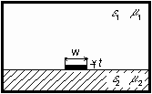
As the second representative of microwave transmission lines, a microstrip transmission line (par. 3.2). is introduced. A microstrip transmission line consists of a relatively narrow strip conductor appearing on the true side of a dielectric substrate. A continuous metallic ground plate of zero potential covers the backside. The whole transmission line is usually placed to a rectangular waveguide, which serves as a shielding. Since we are not able to analyze the described transmission line by purely analytical approach, we perform the analysis numerically - by the finite-element method. | ||||||||||||

