3.1 WaveguidesBasic theoryOur layer of this article brings basic information about the propagation of electromagnetic waves in waveguides. In the layer B, we present a Dutch translation of the article to the reader in order to help him (her) to become familiar with the terminology from the area of waveguides and microwave transmission lines.
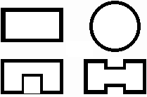
Types of transmission lines we know from our everyday life (coaxial cables, etc.), can be used on microwave frequencies in limited number of applications due to unacceptable losses in the dielectrics of those lines. That is why waveguides are frequently used on higher frequencies. The waveguide usually denotes a metallic cylinder which transversal dimensions are comparable to the wavelength. Inner walls of the waveguide are processed that way which minimizes losses in the metal (walls can be considered as a perfect electric conductor). The transversal profile of the waveguide is usually of the rectangular or circular shape. In special cases, the profile is of the shape of letters Π or H (fig. 3.1A.1); such waveguides are of wider broad-band on one hand but they can transmit lower power on the other hand.
Waveguides can be met on gigahertz frequencies, because on lower frequencies, transversal dimensions of waveguides are too large. Waveguides are exploited in radars and in satellite communication systems. They serve here for the energy transmission from the generator to the antenna and vice versa. Assume a longitudinally homogeneous metallic waveguide of an arbitrary transversal profile (fig. 3.1A.2). Modeling electromagnetic field, which is produced by a source inside the waveguide, is the aim of our computations. Assume that our computations are performed is large distance from sources. Then, computations can be based on the homogeneous wave equations for the longitudinal component of the electric Hertz vector Πze and the magnetic one Πzm. Since the field distribution in the longitudinal direction z is not dependent on the field distribution in the transversal directions u, v, both Hertz vectors can be rewritten as the product of two functions where the first one is dependent on transversal coordinates u, v, and the second one depends on the longitudinal coordinate z, i.e. Πz = T1(u,v) × T2(z). Exploiting the method of variables separation, we yield separation constants Γ and γ, which are related as
In the above relation, Γ is the separation constant that is related to the field distribution in transversal directions, γ is related to the wave propagation in the longitudinal direction and k is wave-number for the free space (vacuum with permitivity ε0 and permeability μ0)
and ω denotes angular frequency. The detailed mathematical description of the above approach can be found in [1]. Solving the equation for the wave propagation in the longitudinal direction in the waveguide, following relation is obtained
C1 and C2 are integration constants. First term describes the backward wave (it propagates in the contra-direction of the axis z), the second term is related to the forward wave (it propagates in the direction of the axis z). The separation constant γ is called the propagation constant and it can be rewritten as
Considering (3.1A.4), β can be understood as the attenuation constant and α as the phase constant. Since the wave-number k is real (a lossless medium is assumed inside the waveguide) and since the separation constant G is real too (as will be shown later), the propagation constant can be of the following values:
Since the wave-number linearly depends on the frequency, an interesting conclusion can be done: whereas waves of lower frequency than
do not propagate in the waveguide, waves of higher frequency than ωkrit propagate without any attenuation. Frequency (3.1A.5) is called the critical frequency.
Let us examine the phenomena appearing on frequencies higher than the critical one f > fkrit. Substituting γ = jα to (3.1A.1), we get
Expressing the separation constant Γ from (3.1A.5) and using wave-number k from (3.1A.2) we get the relation for the phase constant in the longitudinal direction
Substituting the phase constant (3.1A.7) to the relation for the phase velocity
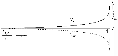
we get dependency of the phase velocity in the waveguide on the frequency
Here, v denotes phase velocity of the wave in free space (vacuum in our case)
Using known phase velocity, relation between phase velocity and wavelength
in the longitudinal direction in the waveguide can be obtained
Here, λ denotes wavelength in free space. If we are interested in the velocity of energy propagation, the group velocity has to be computed. Since the product of the group velocity and the phase one has to equal to the square of the velocity of light, we can compute the group velocity using the following relation:
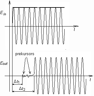
where v is phase velocity in free space. The above computations were performed for the propagation of harmonic waves. If the wave consists of more harmonics then every frequency component propagates with velocity, and therefore, the output signal differs from the input one (the signal is distorted). The described phenomenon is called dispersion (fig. 3.1A.4). Up to now, we dealt with analysis in the longitudinal direction. Results of this analysis do not depend on the shape of the transversal profile, and therefore, they are valid for any homogeneous waveguide. In the transversal directions, the situation is totally different:
The analysis is done for two types of waves, which can propagate in the waveguide, for the transversally magnetic waves (TM, components of the magnetic intensity vector are non-zero in transversal directions only), and for the transversally electric ones (TE, components of the electric intensity vector are non-zero in transversal directions only). Following [1], relations for critical frequencies of waves of both types can be obtained:
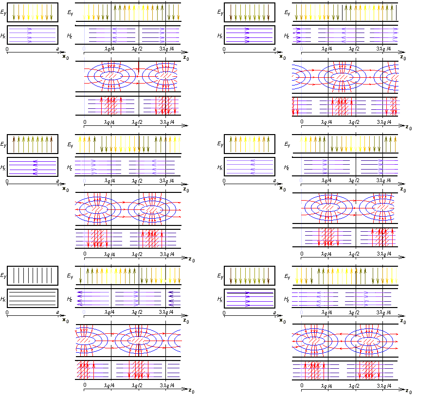
Here, permitivity and permeability are related to the medium inside the waveguide, a denotes the width of the waveguide and b is its height. Integral coefficients m and n are called mode numbers. Increasing mode numbers, critical frequency is increased (therefore, higher modes appear on higher frequencies). Assume that a supplying generator is tuned from lower frequencies to higher ones. Reaching the critical frequency of the lowest mode, a single wave starts to propagate in the waveguide. If the critical frequency of the second mode is reached then two waves of two different modes propagate in the waveguide. Those waves can interfere, which can lead to many problems, Therefore, waveguides operate in the single-mode band usually. The low bound of this band is given by the critical frequency of the lowest mode, the high bound equals to the critical frequency of the second mode. The mode of the lowest critical frequency is called the dominant mode. Let us concentrate on the field distribution of the dominant mode TE10 in the moment t = t0 (see animation).
Cutting the waveguide by a longitudinal wall that is perpendicular to the wider side, a harmonic course of the transversal component of electric intensity Ey can be observed. Maximal intensity in the figure is located to coordinates z = λg/4 and z = 3λg/4 (phase is opposite here). In z = 0 and z = λg/2, electric intensity is zero. In the points of maximal Ey, longitudinal component of magnetic intensity Hz is zero and transversal component of magnetic intensity Hx is maximal. In the transversal cut in z = λg/4, Ey is maximal in the center of the waveguide and zero on walls (boundary condition met). Transversal component of magnetic intensity Hx is in z = λg/4 constant. If the cutting wall is perpendicular to the narrower side of the waveguide, magnetic intensities form ellipses (similarly as in the case of a wire flowing by a current). In case of waveguide, a current flowing from the low wall of the waveguide to the up one through the vacuum produces magnetic field. If the current reaches the wall, it flows in the form of the conducting current on the waveguide wall back. Finally, we can state that the transversal electromagnetic field is distributed that way so that the boundary conditions on perfectly electrically conducting walls are met. This fact is illustrated by the Matlab program for the analysis of the electromagnetic field in the rectangular waveguide by the finite-element method. User's guide of the program can be found in the layer C. A brief introduction to the finite-element method and a brief description of the software implementation are given in the layer D. |


