3.2 Shielded microstrip tranmission linesBasic theory
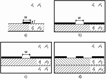
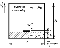
Shielded microstrip transmission line is a member of the family of planar microwave transmission lines. Open microstrip line (fig. 3.2A.1a), shielded slot-line (fig. 3.2A.1b) shielded fin-line (fig. 3.2A.1c) or coplanar waveguide (fig. 3.2A.1d) belong to the most common planar transmission lines. Using segments of planar transmission lines, microwave circuits can be composed. Planar conductors can serve for connecting circuit components or can be used for creating passive circuit elements (capacitors and inductors, especially). Moreover, planar circuits can be relatively simply completed by active elements (transistors and diodes, e.g.). Therefore, the planar technology is of wide use these days and analysis of planar structures is of rising importance. In this paragraph, we deal with the computation of the electromagnetic field distribution in shielded microstrip transmission line (fig. 3.2A.2), which parameters are assumed to be constant in the longitudinal direction. Then, only a two-dimensional structure has to be analyzed (cross-section of the transmission line), which simplifies computation [20].
Even if the above-described simplification is done, field distribution in the shielded microstrip transmission line cannot be computed analytically. Therefore, numerical methods or approximate ones have to be exploited. All the methods can be divided into two groups, to quasi-static methods and to full-wave methods [20]. Quasi-static methods are based on the assumption that the dominant mode of the wave, which propagates along the transmission line, can be approximated (with good accuracy) by the transversal electromagnetic wave (TEM). Unfortunately, this assumption is valid on low microwave frequencies (typically by 5 GHz). If frequency is increased, then the value of longitudinal components of electromagnetic field rises, and hence, it cannot be neglected. Working on higher microwave frequencies, full-wave methods have to be exploited for the analysis. Full-wave methods are based on the direct solution of Maxwell equations. Since the transmission line is going to be analyzed in the harmonic steady state, Maxwell equations are of the following form:
Here, E denotes electric-field intensity vector, H is magnetic-field intensity vector, operator nabla is in Cartesian coordinate system of the form
JS denotes density of currents, which are imposed to the analyzed system by sources, ω is angular frequency, ε0 and μ0 are permittivity and permeability of vacuum, εr and μr denote relative permittivity and permeability of dielectrics inside the analyzed structure, ρ is volume charge density in dielectrics and σ denotes electric conductivity of dielectrics. Assume that sources of electromagnetic field are in a large distance from the area where computations are performed (then, imposed currents Js are zero in this area). Next, zero charge density is supposed in the structure and the media are expected to be linear and isotropic (permittivity and permeability are scalar quantities, which do not depend on the value of respective field intensities). Further, dielectrics are assumed to be lossy (represented by electric conductivity σ) and all metallic parts (shielding waveguide, microstrip) are expected to be perfect electric conductors. All the assumptions are substituted to (3.2A.1). Then, both sides of (3.2A.1a) are multiplied by the operator nabla from left (in vector way). That way, curl of the magnetic-field intensity vector is obtained on the right-hand side of (3.2A.1a), which is replaced by the right-hand side of (3.2A1b). Finally, the following equation is obtained:
If the square of wave number in vacuum is denoted as
and complex relative permittivity of dielectrics as
eqn. (3.2A.2) can be rewritten to
Analyzed microstrip transmission line is situated to the Cartesian coordinate system (coordinates x and y in transversal directions, coordinate z longitudinal). Hence, electromagnetic wave propagates along the axis z (along microstrip) and electric-field intensity vector depends on the longitudinal coordinate according to
where γ is propagation constant
β is attenuation constant and α denotes phase constant. Mathematical description of electromagnetic wave propagating in the direction z (3.2A.6), is substituted to vector equation (3.2A.5). Then, all the partial derivatives according to z can be evaluated (respective terms are multiplied by the propagation constant -γ). Rewriting all vectors in (3.2A.5) as a sum of the transversal component and the longitudinal one
we get
Where as (3.2A.9a) is vector equation of transversal components, (3.2A.9b) is scalar equation of a longitudinal component. The set of differential equations (3.2A.9) has to be completed by boundary conditions, which have to be met by the solution of (3.2A.9)
Eqn. (3.2A.10a) describes the fact that components of electric-field intensity vector, which are tangential to the perfectly electrical-conductive surfaces Γ1, have to be zero on those surfaces. Eqn. (3.2A.10b) expresses the fact that variation of components of electric-field intensity vector in the normal direction with respect to perfectly electric-conductive surface Γ2 has to be zero on this surface. Eqn. (3.2A.9) completed by boundary conditions (3.2A.10) are the initial relations to the full-wave analysis of microstrip transmission line. We have to keep in mind, that eqns. (3.2A.9), (3.2A.10) cover the first Maxwell equation and the second one only, and therefore, the solution has to be checked to meet the third Maxwell equation and the fourth one. In the opposite case, the solution would be physically non-existing (spurious one). In the following paragraphs, we describe the way of implementing the full-wave analysis of a shielded microstrip line, which is based on (3.2A.9) and (3.2A.10), by finite-element method. First, we briefly comment physical phenomena in the investigated structure because success of the analysis is conditioned by their correct modeling. First, consider a hollow rectangular waveguide (inside, vacuum is assumed). In such waveguide, a transversal electric wave (longitudinal component of magnetic intensity is present) or a transversal magnetic one (longitudinal component of electric intensity is present) can propagate. If a dielectric substrate is inserted into the waveguide (filling becomes inhomogeneous), longitudinal components of both the electric-field intensity and the magnetic-field one appear in the structure at the same time. In the opposite case, boundary conditions could not be met at the interface between dielectric and vacuum. Wave propagation in a waveguide of inhomogeneous filling can be described by hybrid modes LSM (Longitudinal Section Magnetic) and LSE (Longitudinal Section Electric). Moreover, in inhomogeneous filling is completed by a metallic microstrip, transversal and longitudinal currents are induced there, which mutually couple LSE and LSM modes. Numerical analysis of wave propagation in a metallic waveguide (vacuum inside) is relatively simple because homogeneous wave equation is needed to be solved for the longitudinal component of electric-field intensity (modes TM) or magnetic-field one (modes TE). If microstrip transmission line is going to be analyzed, attention has to be paid to two potential sources of spurious solutions. First, production of spurious solutions can be caused by incorrect modeling of electromagnetic conditions on the boundary between the substrate and vacuum. Second, incorrectly modeled influence of metallic strips can cause appearance spurious solutions. Exploiting hybrid finite elements can eliminate both the causes. Analyzing a shielded microstrip line by hybrid finite elements, all the components of electric-field intensity or magnetic-field one have to be included into the computations. Eqn. (3.2A.9) is the initial relation of the analysis. Matter of hybrid finite elements consists in modeling a longitudinal intensity component using nodal approximation, and transversal intensity components using an approximation, which is based edge vectors. Turn our attention to the general solution of (3.2A.9) under conditions (3.2A.10) by finite-element method. At every step of the general approach, we discuss the operation of the method in our situation. First, an analyzed structure is subdivided into sub-spaces (finite elements), which do not overlap and which cover all the points of the structure. In the space of a finite element, parameters of the analyzed structure (permittivity, permeability, conductivity) have to be constant. There are no restrictions to size and shape of finite elements. Finite-element mesh can be denser in areas where details of the solution are of our interest, and can be relatively sparse in areas where details are out of our interest. Finite elements can be curvilinear, and therefore, an arbitrary geometry can be modeled. Analyzing longitudinally homogeneous microstrip transmission line, two-dimensional problem is solved. Therefore, we turn our attention to two-dimensional finite elements. Leaving piecewise constant approximation, a linear function is the simplest approximation function. In two dimensions, the linear function is a plane over a finite element (the computed quantity can be imagined to be drawn above the element).
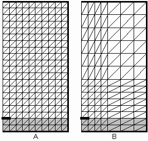
If three points uniquely determine the approximation plane, the analyzed structure is subdivided to triangular finite elements. Coordinates of vertexes of triangular finite elements are independent variables of the two-dimensional linear approximation. Samples of sought field distribution are dependent functional values. Interlaying the approximation plane through the dependent functional values in triangle vertexes, a unique approximation plane is obtained. The analyzed structure has to be divided to finite elements very carefully because both the final error and CPU-time demands of the analysis strongly depend on the mesh geometry. In fig. 3.2A.3, two examples of triangular finite-element meshes for the analysis of shielded microstrip line are depicted. For simplicity, two triangular finite elements create a rectangular bi-element together, which is the basic building block of our mesh. Mesh A is homogeneous (consists of identical finite elements). Since electromagnetic field can be expected to quickly decrease with the distance from the microstrip, distant areas can be covered by a sparser mesh B. As shown later, the mesh B negligibly decreases accuracy of the analysis, but significantly reduces CPU-time demands (lower number of finite elements corresponds to lower number of mathematical operations). In the second step of the solution, an approximation of a sought function over each finite element is expressed in a formal way. Usually, the unknown solution is approximated by a linear combination of elected approximation functions and unknown approximation coefficients. A linear function is the simplest approximation. As an example, we consider a general plane, which is uniquely determined by functional values of the approximated function in three points of a finite element. This general plane can be composed of three sub-planes (a linear combination), each of which is unitary in a single points of a finite element and which is zero in other two points of a finite element. Unknown approximation coefficients, which appear in the linear combination at partial planes, play the role of spatial samples of the spatial distribution of computed quantity in points, where partial functions are of unitary value (other functions are zero in this point, and therefore, they do not participate in sampling). For the longitudinal component of electric-field intensity, we get therefore
where Ez(n) is an approximation of a sought function over nth finite element, cm are unknown approximation coefficients and Nm(n) are elected partial approximation functions on nth finite element, Mn denotes the number of partial approximation functions exploited for composition of the total approximation of sought function over nth finite element. Collecting approximations over all N finite elements, a global approximation over the whole analyzed structure is obtained
Eqn. (3.2A.12) is a single equation for M unknown approximation coefficients cm. If these coefficients are found, approximation of the sought quantity is obtained. More information about above-described approximation can be found in the layer B. In the third step, the formal approximation of the solution Ez~ is substituted to the solved partial differential equation. Since the approximation differs from the exact solution, the initial equation is not met perfectly. This fact is respected by introducing a residual function, which equals to the difference between the exact solution and the approximation
The approximation is as accurate as low values of the residual function are. Therefore, we are going to minimize the residual function over the whole analyzed structure. The residual function is minimized exploiting the method of weighted residuals. The method of weighted residuals consists in multiplying the residual function R(x, y) by a weighting function W(x, y). The product is integrated over the whole analyzed space S and the result is set to equal zero
where dS = dx dy. If as many properly elected weighting functions Wn are used as many unknown approximation coefficients are computed, a set of linear equations (as many equations as unknown approximation coefficients) is obtained. Solving this set of equations, unknown approximation coefficients are obtained. If partial approximation functions of nodes, where nodal quantity is unknown, are elected as weighting functions the method of weighted residuals comes to Galerkin method. For nth finite element, the final matrix equation is of the form
where
In the above relations, Et(n) is unknown column vector of edge approximation coefficients (approximation of transversal components of electric-field intensity) over nth finite element and Ez(n) denotes column vector of three unknown nodal approximation coefficients (approximation of longitudinal component of electric-field intensity) over nth finite element. Next, γ denotes complex propagation constant, k0 is wave number in vacuum, μr(n) is relative permeability of nth finite element and ε~r(n) is complex relative permittivity of the same element. Symbol dS denotes an elementary facet for the integration over nth finite element and symbol S(n) give the total surface of nth finite element. Summation including index m symbolizes addition over all nodes of a finite element (i.e., m = 0, 1, 2) a summation including indexes i, j symbolized addition over all edged of an element (i.e., i, j = 0-1, 1-2, 2-0). Symbols et, ij(n) are edge approximation coefficients, symbols ez, m(n) are nodal approximation coefficients. Matrices Tt(n), G(n), Sz(n), Tz(n) and St(n) matrices of coefficients of nth finite element of the size 3 x 3. Elements of the above matrices are computed by integration of the product of partial approximation functions and weighting functions (or their derivatives) over nth finite element. Matrices can be evaluated using the following relations
where
A(n) is surface of nth finite element and θi(n) is angle at ith vertex of nth finite element. Given relations are valid for the following organization of nodes and edges
If the matrix equation is solved out for the vector of unknown approximation coefficients, then solution of the problem is obtained. Substituting approximation coefficients to the formal approximation, a real approximation of a sought function in each point of nth finite element is obtained. Joining approximations over all finite elements, the global solution is found. In the layer C, the reader can find a matlab program for the finite-element analysis of a shielded microstrip transmission line. Prom the programmer's point of view, the program is described in the layer D. |


