3.2 Shielded microstrip tranmission linesDeveloping MatlabSoftware implementation of the finite-element method applied to the analysis of a shielded microstrip transmission line is similar to the analysis of waveguides (part 3.1, layer D). Therefore, we briefly discuss common features and differences of the approaches.
 |
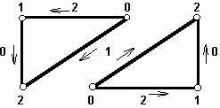
| Fig. 3.2D.1 | Numbering local edges |
|
Numbering of nodes and edges. Local numbering of edges stays the same as given in the description of the analysis of rectangular
waveguide. Considering triangles lying on the edge, numbering starts at the left
down vertex and continues in the anti-clockwise direction. Considering triangles
standing on a vertex, numbering starts at the right upper vertex and continues in
the clockwise direction. Number of a local edge is then given by number of the
opposite vertex. The described numbering is depicted in fig. 1.
The global numbering starts by numbering diagonal edges from the left down element and continues through rows of finite bi-elements
to the upper right element. Then, the numbering continues the same way for horizontal
edges and for vertical ones. At the end, nodes are numbered the same way as in the
case of rectangular waveguide.
Nodes and edges can be numbered by an arbitrary way (the described numbering is nor compulsory). Nevertheless, the numbering
convention has to be kept in the whole program, i.e., when the matrix C is built, when local nodes and edges are associated to global ones,
when boundary conditions are introduced, when results are visualized, etc.
 |
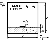
| Fig. 3.2D.2 | Shielded microstrip transmission line |
|
- Composing matrix C. The matrix C
serves to associating local edges and nodes to global ones. The part of C related to associating nodes
stays the same as in the case of a rectangular waveguide (in the first column, ones
are put to all rows, which correspond to local nodes associated to the first global
node, etc.). The part of C, which associates local edges, contains maximally two
ones in a column (maximally two local edges can form the global one). Moreover,
one of ones has to be negative because two neighboring edges are of the opposite
orientation (see fig. 1).
- Boundary conditions. Analyzing the
structure, we have to ensure that electric-field intensity components, which are
in parallel to perfectly electric-conducting surfaces, are zero. Therefore, we have
to eliminate those columns and rows of global matrices, which correspond to nodes
and edges on such surfaces. Moreover, we have to eliminate columns and rows, which
correspond to nodes and edges inside metallic parts.
Except for the above-described exceptions, the program is identical comparing to the program for the analysis of a homogeneous waveguide.
|

