4.1 Drátový dipólPodrobnější popisIn this chapter, we introduce the reader to the moment-method computing of parameters of a wire dipole. We present all the information in English in this layer so that the reader can become familiar with English terms, which are used in the area of antennas and computational electromagnetics. The Dutch translation of this chapter can be found in the layer B.
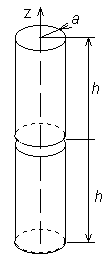
All the technical parameters of antennas (gain, input impedance, directivity pattern) can be computed if current distribution on the antenna surface is known. Unfortunately, computation of current distribution makes troubles because integral equations have to be solved. There are two basic approaches to the solution of integral equations – iterative and moment ones. Iterative methods are based on rough approximation of the current distribution (e.g. sinus one) that is iteratively made more accurate. On the other hand, moment methods transform integral equations to a set of simultaneous linear equations, which are solved by matrix operations. In this chapter, our attention is turned to the moment analysis of wire antennas. In all the cases, antennas are supposed to be circular cylinders of the radius a and of the length 2h. The antenna axis is situated to the axis z (fig. 4.1B.1) of the cylindrical coordinate system (r, ρ, z). The antenna is placed to the vacuum (μ = μ0, ε = ε0, σ = 0) and no losses are considered.
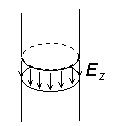
In the center of the cylinder (z=0), there is a short gap. In the gap, we assume a hypothetical harmonic generator, which produces an azimuthally symmetric exciting electrical field (fig. 4.1B.2). The voltage across the gap
is supposed to be 1V. In (4.1B.1), Ez is the z-component of the exciting electrical field intensity on the interpolated antenna surface (fig. 4.1B.2). Outside the gap, Ez is zero due to the perfect conductivity> of the cylinder. I. Methods of Moments Let us to consider a general integral equation
where f is an unknown function, <a,b> is the integration interval and g is a known function describing sources. The moment solution of (4.1B.2) can be reached within 3 steps:
II. Basis Functions Basis functions can be global or local ones. Global basis functions are defined on all the region of interest <a,b>. E.g., system of functions
is on <a,b> linearly independent and coefficients cn in the approximation
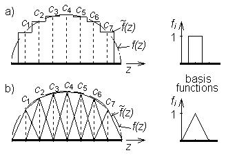
have got then meaning of Fourier coefficients of the current distribution. Approximation based on the global basis functions is called the single-basis approximation. Local basis functions are defined on all the region too but each of them is non-zero only on a sub-region of the interval of interest <a,b> as can be seen in fig. 4.1B.3. If basis functions are normalized then coefficients cn have got the meaning of nodal values (samples) of the computed function f (fig. 4.1B.3). Approximation based on the local basis functions is called the multi-basis approximation. III. Weighting functions Point matching and Galerkin’s methods are the most common ways of the residuum minimization. Point matching (or collocation) uses Dirac pulses, which are place to points where the values of unknown current distribution are computed, as weighting functions
Point matching method exhibits very low computational requirements because one integration is eliminated in 4.1B.5b) thanks to the filtering property of Dirac pulses
On the other hand, the residuum minimization is related to the matching points zm only. In Galerkin’s method, weighting functions are identical with basis ones
Galerkin’s method exhibits higher computational requirements in comparison with point matching because one of integrations is not eliminated in this case. On the other hand, the residuum minimization is performed with all the points z ∈ <a,b>. IV. Wire antennas Assume the cylindrical antenna of fig. 4.1B.1. Then, the radiated electromagnetic field can be expressed in terms of vector potentials A and scalar potentials φ, respectively. Potentials have to meet inhomogeneous wave equations [2]
Here, Jz is the z-component of the current density [A.m-2] impressed to the antenna by the source, ρ is the volume charge density [C.m-3] on the antenna, Az is the z-component of the vector potential and φ is the scalar potential, k=2π/λ is the wave-number and λ is the wavelength. The current flowing on the antenna causes charge accumulation at the antenna cylinder. This fact can be described by the continuity equation [2]
If radius of the antenna cylinder is much smaller than the wavelength a << λ then the current and charge can be assumed to be concentrated in the axis of the cylinder [5], and solving (4.1B.11) yields [2]
Here, Iz(ξ) is the current [A] flowing in the axis of wire, σ(ξ) denotes the length charge density [C.m-1] on the axis of wire, R(z,ξ) is the distance between the location ξ of electromagnetic field sources Iz(ξ) and σ(ξ) and the location z potentials A(z) and φ(z). On the basis of A(z) and φ(z), electrical intensity of the field radiated by the antenna can be computed [2]
Electrical intensity has to meet the boundary condition on the antenna surface S
Ezi denotes electrical intensity of the incident wave. In the case of an usual transmitting antenna, Ezi is the intensity by the feeding source (on the antenna surface), i.e. the intensity in the exciting gap (fig. 4.1B.2). If the current distribution on the antenna is to be computed then the set of equations (4.1B.12) has to be solved. In order to meet the boundary condition 4.1B.12e), electrical intensity (and consequently potentials) has to be computed on the surface of the wire. That is why the distance R is described by the equation
In the following paragraphs, piece-wise constant basis functions and Dirac weighting functions are used to solve (4.1B.12).
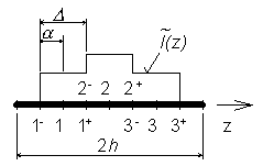
In the first step, the analyzed structure has to be discretized. Segmentation of the antenna is depicted in fig. 4.1B.4. Lower bounds of segments are signed by ”-”, upper ones by ”+”. Lower bound of the first segment and upper bound of the last one are shifted from the ends of the antenna in order to meet the condition I(-h)=I(h)=0. Segments’ lengths are Δ = 2α. Substitung piece-wise constant approximation to the integral equations 4.1B.12b,c) yields
Here, In and σn are nodal values of current and charge density distributions. Since the first derivative of the piece-wise constant approximation is zero on the constant sections and does not exist on their borders, 4.1B.12a) and 4.1B.12d) are rewritten in terms of finite differences. If the fact that In = Iz(-h+nΔ) is considered then the continuity equation can be expressed as
and the relation for computing electrical intensity is then of the form
Relations 4.1B.15a) and 4.1B.15d) show that Dirac pulses for point matching have to be placed to the center of segments for the vector potential
and to borders of segments for the scalar potential
In 4.1B.15c), σn+ = σ [-h+(n+0.5)Δ]. Now, (4.1B.15) can be rewritten into a more compact form
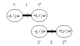
In 4.1B.16d), the boundary condition 4.1B.12e) is included. Now, let’s have a look at the continuity theorem 4.1B.16a); it expresses the fact that segments of the antenna can be replaced by elementary electrical dipoles (fig. 4.1B.5). Taking this idea in mind, submission of nth segment to the scalar potential can be computed on the basis of 4.1B.16c) as
Substituting (4.1B.17) and 4.1B.16b) to 4.1B.16d) and multiplying both sides by Δ yields
where
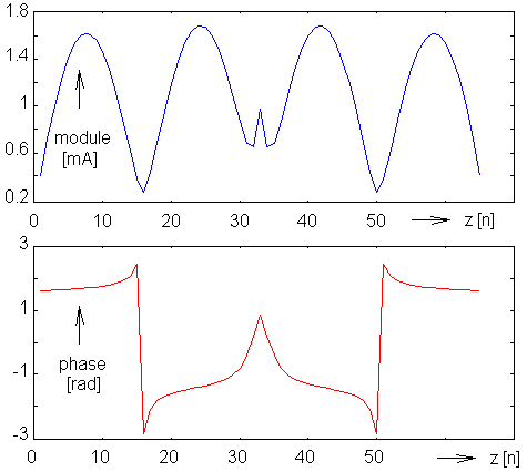
denotes submission of current and charge on nth segment to the voltage induced on the mth segment. Since electrical intensity is zero on all the segments except of the source gap, elements of voltage vector are zero except of the gap-segment corresponding element that equals 1. Then, (4.1B.18) provides the current distribution I. Ratio of input voltage and input current gives then the input impedance of the analyzed antenna. An example of the analysis results is depicted on fig. 4.1B.6; module and phase of the current distribution of the dipole h = λ and a = 0.001588 λ is plotted there. The presented results (fig. 4.1B.6) can be obtained using a computer program, whose user’s guide is presented in the layer C. In the layer D, the program is described from the programmer’s point of view.
|
