4.4 Microstrip dipoleAdvanced theory
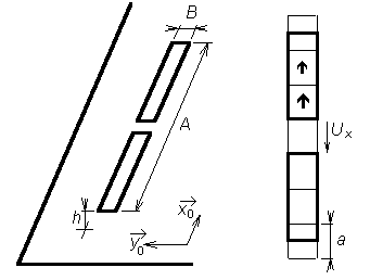
As a microstrip dipole, we denote an antenna consisting of two narrow microstrip arms, which are fed by a symmetric source in the center. The antenna is placed on an upper side of the dielectric substrate. The bottom side of the substrate is fully covered by a metallic layer and I of zero potential (fig. 4.4B.1). Effects of currents flowing on the antenna can be described by vector potential
Effects of charges on the antenna can be described by scalar potential
In the above-given equations, A(r) denotes vector potential in the point r, J is current density vector in the point r0, GA is dyadic Green function and GV denoted scalar Green function (see the layer D). The parameter of Green functions r|r0 tells us that we compute the contribution of a current (charge) from the point r0 to potentials in the point r. The symbol r denotes charge density. Current density and charge one are mutually associated by the continuity equation
If both the vector potential and the scalar one are expressed on the surface of the microstrip dipole, we can evaluate electric intensity of a wave, which is radiated by the antenna.
Applying (4.4B.1) to the microstrip dipole from fig. 4.4B.1 and substituting from continuity equation to (4.4B.1b), we obtain the following relations
Here, Ax denotes x-component of vector potential and V is scalar potential, GAxx denotes x diagonal element of dyadic Green function and GV is scalar Green function, Jx is x-component of sought vector of current distribution and Ex is x-component of the radiated electric field intensity. Details are given in the layer A. Substituting vector potential (4.4B.2a) and scalar one (4.4B.2b) to the relation (4.4B.2c), we obtain the initial equation for moment analysis of the dipole
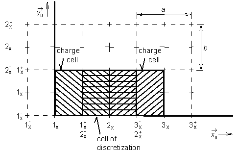
Magnitude of electric field intensity on the surface of the microstrip dipole can be computed using a boundary condition if perfect conductivity of metallic parts is assumed (except of the excitation gap, the intensity is zero). Therefore, x-component of current density Jx is the only unknown in (4.4B.3). In the first step, surface of the dipole is divided into discretization elements. Center of the first discretization element is denoted by 1, center of the second element by 2, etc. The upper bound of the discretization element is denotes by the same number completed by superscript "+" (plus), the lower bound by superscript "-" (minus); see fig. 4.4B.1. Next, points in the center of discretization elements are used for computing x-component of electric field intensity. Since contribution of the current to the magnitude of electric field intensity is described by vector potential without presence of derivatives (see eqn. 4.4B.2), vector potential is computed in the center of elements. On the contrary, contribution of charges to electric field intensity is described by scalar potential performing two derivations according to x. In numerical computations, derivations are replaced by central differences. Values of scalar potential V, which derivatives are used for determining contributions of charges to the electric intensity of the radiated wave, have to be known at the borders of discretization elements so that the result of central differentiating appears in the center of the element. Values of charge density are computed from continuity equation deriving components of current density in centers of discretization elements (derivatives are replaced by central differences again). In order to obtain values of charge density on the border of elements, we have to differentiate components of current distribution in the center of elements. This fact suits us very well because the computed values of current density are valid just in these points. Finally, values of current density components are computed in the center of elements and values of charge density have to be evaluated on borders of the elements. Therefore, value of components of vector potential and value of components of electric field intensity are valid for the center of elements, and value of scalar potential for border of elements. In the next step, we substitute piecewise constant approximation of current distribution to initial relations and we replace partial derivatives by central differences. Exploiting continuity equation, charge density on the upper edge and on the low one of the discretization element is expressed
Symbol a height of the discretization element (see fig. 4.4B.1), Jx(mx, nx) corresponds to a constant value of x-component of current density vector on the surface of the element containing the central point mx, nx) and ω is angular frequency. On the basis of equations (4.4B.4a) and (4.4B.4b), we compute contribution of charges, which are represented by charge density ρ, to the x-component of electric field intensity vector. Considering charge densities of the upper edge ρ(mx+, nx) and on the low one ρ(mx-, nx), scalar potential on those edges can be computed. Moreover, substituting partial derivatives according to x by central differences, we obtain contribution of charges to x-component of electric field intensity. Now, charge densities on borders of discretization elements are known and we assume that those values are valid not only on the borders but too over the whole surface of charge elements (they are of the same size as discretization elements but they are shifted so that borders of discretization elements can be in the center of charge ones as depicted in fig. 4.4B.1). Then, charge densities can be described by the following piecewise constant functions
In these relations, Π(xm+, yn| x,y) denotes a function, which is unitary in the rectangular region with the center in (xm+, yn), a is height of the element and B is its width. The similar situation is for points (xm-, yn). Values of charge density ρ(xm+, yn) and (xm-, yn) in the center of this rectangular region are given by relations (4.4B.5). If charge density on the microstrip dipole is known, we can substitute the distribution to and we can compute scalar potential on respective charge elements. For the charge element, which center lies on the upper edge of the element (mx, nx), we get
and similarly for V(mx-, nx).
Before continuing, let us discuss the relation (4.4B.6). Rearranging it, we swapped integration and summation, and the integral of the product of the unitary pulse Π and the scalar Green function GV over the whole dipole was substituted by the integral of the single scalar Green function over the surface of this charge element, where π is non-zero. Dealing with indexes, (m, n) determines position of the observation element, over which the value of scalar potential is computed, and indexes (p, q) specifies position of the source element, whose charges contribute to the scalar potential of the element (m, n). Scalar Green function GV is the only continuous function in (4.4B.6), and therefore, the integral has to be evaluated for this function only. Evaluating this integral for various distances between the source element and the observation one, position of the observation element is changed only, and the source element stays in the origin of the coordinate system. Therefore, integration limits stay the same in all the cases (from -a/2 to +a/2 for the coordinate x' and from -B/2 to +B/2 for the coordinate y'). Now, constant values of scalar potential are known over all charge elements. Therefore, we can compute contribution of charges, which are represented by scalar potential, to the values of x-component of electric field intensity
Here, a denotes height of the element, B is the width of the element, and values of scalar potential V over charge elements are given by the relation (4.4B.6). As already said, we are aimed to express an approximation of electric field intensity of the radiated wave on the surface of the dipole as a function of current density on this dipole. Hence, we substitute (4.4B.6) for scalar potential V on the border of elements, which enforces (4.4B.7) to be a function of charge density r on edges of elements
In the above-given relation, a denotes height of element and B is its width. Angular frequency ω corresponds to the frequency, on which antenna is analyzed. The symbol VExS denotes a contribution of scalar potential V to the magnitude of x-component of the vector of electric intensity of the radiated wave. Finally, GV represents integral of scalar Green function GV over the surface of the element
As the next step in expressing electric field intensity as a function of current density, values of charge density from (4.4B.5) are substituted to (4.4B.8)
The relation describes the contribution to the component of the vector of electric field intensity using unknown values of the component of current distribution vector Jx and known coefficients ΓV, given by (4.4B.9). From the point of view of scalar potential, the aim was reached, and therefore, the attention is turned to the vector potential. In order to evaluate the contribution of the current to the electric field intensity, we have to compute vector potential substituting piecewise constant approximation of current density to (4.4B.2a)
In the above-given relation,
Next, a is height of the discretization element and B is its width. GAxx denotes x diagonal component of dyadic Green function. Function Π(px, qx| x',y') is unitary over an element with the center in the point (px, qx) and is zero elsewhere. Values Jx represent piecewise constant current density in the element mesh (px, qx). During derivation, integration and summation were swapped, and integral over the whole dipole surface S was replaced by the integral over a single element (due to multiplying by Π the integrand is non-zero over a single discretization element only). Finally, substituting vector potential to (4.4B.3) and replacing derivatives of scalar potential by contributions (4.4B.10), we obtain the final equation
Since eqn. (4.4B.13) is rather complicated, we rewrite it into a matrix form
Here, Ux is column vector of voltages in the direction x over elements. Voltages are computed by multiplying x-component of electric field intensity by x-dimension of the discretization element
The symbol a denotes height of the discretization element (i.e. the element dimension in the direction x). Since the microstrip dipole is assumed to be fabricated form perfect electric conductor, the vector of voltages consists of zeros only (except of excitation elements). Next, Ix is column vector of unknown current in the direction x. Elements of Ix are related to current density Jx by the equation
(B is width of the dipole, and therefore, even the width of the discretization element). Impedance matrix Zxx describes contributions of currents Ixx and contributions of charge densities r to voltages Ux over elements. Single elements of the impedance matrix Zxx are obtained comparing (4.4B.13) to (4.4B.16)
In order to evaluate impedance matrix Zxx, we have to know values of integrals of Green functions over the surface of the discretization element for different distances between source elements and observation ones. Numerical computation of those integrals is described in the layer D. The Matlab program for the analysis of the microstrip dipole by the moment method is described in the layer C from user's point of view. | |||||||||||||||||||||||||||||||||||||||||||||||||||||||||||||||||||||||||||||||||||||||

