4.5 Microstrip antennaBasic theoryWe become familiar with the patch antenna in the paragraph describing the analysis of the wire dipole (par. 4.4) already. Nevertheless, we left this antenna and concentrated on the one-dimensional moment method for the analysis of a dipole. Since patch antennas play a significant role in today's wireless communication systems, we pay our attention to its analysis in this special part of the textbook. In the introductory part, architecture and properties of patch antennas are described. Then, two ways of the antenna analysis are explained. Finally, accuracy and computational demands of those two methods are compared. In the appendix, an overview and basic features of commercial programs for the analysis of patch antennas are given. I. Introduction First notes on patch antennas appeared in the literature at the beginning of fifties of 20th century. This time, planar antennas, which can meet the surface of airplanes and military equipment, were demanded. Later, patch antennas were intensively exploited even in the civic are (in communication especially).
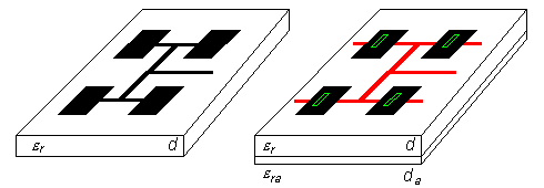
These days, a plenty of various types of patch antennas are at our disposal. These antennas differ in the shape of antenna elements (rectangular, circular), in polarization they operate with, in feeding (in par. 4.4, microstrip and coaxial feeding were described), etc. In our description, we concentrate on rectangular patch antennas fed by a microstrip transmission line. We subdivide path antennas into two groups depending if the feeding microstrip is placed on the same side of the substrate as the antenna element (classical patch antenna, fig. 4.5A.1a) or not. The second (newer) case is going to be investigated more intensively. Within last 15 years, indirect feeding of patch antennas is frequently used. For this purpose, small coupling slots in the ground plane are utilized. These slots are usually positioned in the center of antenna elements. Below the slot, where the feeding microstrip is placed, a certain (inductive) impedance can be observed. This impedance physically represents an antenna element, which exhausts energy from the microstrip transmission line. The microstrip crosses the slot and continues further (see overlaps in fig. 4.5A.1) in order to compensate the reactive part of the above-mentioned impedance by the shunt. Antennas, which are fed by the described way, are for simplicity called aperture-fed patch antennas. Both groups of antennas exhibit some similarities and some differences (see tab. 4.4A.1). Small impedance bandwidth is a common property of patch antennas. For classical patch antennas, the bandwidth is about 2 to 3%, for aperture-fed antennas about 4 to 6%. High quality factor of patches is the reason. Patches behave as a resonator of a quality factor of several tens. Antenna efficiency is another important parameter. Radiation efficiency (computed for lossless antenna) is given by the ratio of radiated power (integrating Poynting vector in the far region over the whole half-space) and real power on the input port of the antenna (element). Energy, which is not radiated by the antenna, is taken away in the form of surface waves along the infinite dielectric substrate (in real situation, the substrate is limited, of course). From the practical point of view, the total efficiency is important. Except of losses in dielectrics, surface-wave losses contribute to its value. Surface-wave losses are extremely undesired. Lossy dielectrics guiding surface waves can be imagined as a lossy transmission line. Exploiting a limited substrate, standing waves are formed in the substrate. Higher losses are related to higher standing wave ratio. Increase of losses due to the increase of standing wave ratio is called surface-wave losses. The total efficiency of patch antennas is for 1 to 2 dB worse that the efficiency of reflector antennas. Patch antennas exhibit very good cross-polarization. This parameter is not important for antennas operating linearly polarized waves. Designing a dual antenna exhibiting high polarization isolation, this parameter is of high importance.
II. Analysis of stand-alone antenna element There are many methods for the analysis of a stand-alone antenna element. We are going to describe three methods, which are of the most frequent use. Two of the are going to be explained in detail. The first method of the analysis understands the antenna element as a wide microstrip transmission line. As the radiation source, fringe electric fields are considered (fig. 4.5A.2a). The second method of analysis consists in replacing the space below the antenna element by a lossy resonator. Then, input impedance can be computed using the theory of cuboidal cavity resonators [14]. In that case, zero normal component of electric field intensity is assumed on sidewalls of the resonator (see fig. 4.5A.2). Hence, sidewalls can be understood as perfect magnetic conductors. Numerical analysis of the antenna element is the third method. The numerical analysis is based on the moment method, which is formulated in the spectral domain or in the spatial one (this formulation was introduced in par. 4.1, par. 4.3 and par. 4.4). Even here, we concentrate on the moment method in the spatial domain.
II.I. Analysis of a stand-alone element by the transmission line method The method excels in simplicity on one hand, and enables to reach a good accuracy on the other hand. Accuracy of computing input impedance of the antenna element depends of the choice of antenna model. In this paragraph, the simplest model considering radiating slots between two neighboring antenna elements only is assumed (tangential fringe components of electric field intensity are considered as a single source of radiation). The other effects (mutual coupling among radiation sources, radiation of marginal edges) are neglected. Designing the antenna, the admitance of the radiating slot YS (arrows in fig. 4.5A.2) has to be known [14]
Here, W denotes length of the slot [m], w width of the slot [m] (it equals to the height of the substrate d approximately), λ0 denotes free-space wavelength [m], k0 is free-space wave-number (k0 = 2π/λ0) [m-1] and Z0 is free-space impedance [Ω]. In the relation, influence of the permittivity of the substrate is not included because the constant magnitude of electric field intensity is considered along the whole slot. Designing the antenna, the length of the antenna element is chosen (0.48 ÷ 0.49) λ/2, where λ = c/[f (εeff)1/2] and where the effective permittivity of the substrate εeff is computed using quasi-static relations or numerically (computing effective permittivity or characteristic impedance of microstrip transmission line, a proper computer program has to be chosen (several programs do not properly model the dispersion of the transmission line on higher frequencies; hence we recommend Txline from AWR, or TRL85 in Serenade 8.5SV). The length of the antenna element does not equal exactly to the half of the wavelength because the capacitive impedance of the right-hand slot has to be transformed to the inductive impedance so that the capacitive impedance of the first slot on the frequency f can mutually compensate the inductive one. In the second step, such width W of the antenna element is chosen so that the desired resonant resistance of the antenna element is obtained. This resistance can be expressed as Rrez = (2 GS)-1, where GS is the real part of the slot admitance
Substituting free-space wavelength λ0 and free-space characteristic impedance Z0, we get
Choosing W = λ0/2, the resonant resistance equals to 120 Ω. The described model of the antenna element is valid for electrically thin substrates only (we assume d / λ ≈ 0.01, where d is the height of the substrate). If the resonant resistance is required to be higher than 120 Ω, the length of the antenna element W has to be smaller than one half of the wavelength. Resonant resistance cannot be significantly increased because its maximum value cannot be (respecting feasibility of the feeding microstrip) higher than 150 Ω. If impedance transformer is exploited, then the antenna element of the impedance about 240 Ω can be used. Optimizing the width of the antenna element by extending its length is not recommended due to the spatial reasons and functional ones (parasitic resonance and parasitic lobes can appear). Satisfactorily small radiation resistance can be achieved by feeding the antenna element near its center instead of the edge feeding. An example of the design of a stand-alone antenna element is given in the layer C including user's guide of an accompanying Matlab program. II.II. Analysis of a stand-alone element by the moment method Applicability to the limited number of shapes of the antenna element and to the electrically thin substrates is drawback of the transmission-line method. In order to analyze elements of a general shape and elements on electrically thick substrates, the moment method has to be used. The planar antenna element (two-dimensional one in contrast to par. 4.4) is assumed to be fed by a microstrip transmission line. Computing the input impedance of the antenna in the position of the microstrip input is the aim of the analysis.
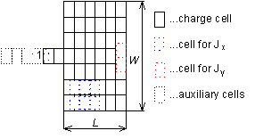
On the antenna element, there is a given current and charge distribution (in reality, a current is distributed over the antenna element). In order to compute the input impedance, currents and charges have to be computed first. Then, another quantity (electric field intensity, magnetic field intensity, input impedance, etc.) can be computed. Since the moment analysis was in detail described in par. 4.1, par. 4.3 ane par. 4.4, a brief overview is presented here only:
A detailed description of the analysis is rather complicated, and therefore we refer to the layer B. Further information is given in [15]. An example of moment analysis of 2D structures is given in the layer C. Finally, we provide an overview of commercial programs, which are based on moment method.
In some aspects, the above-given programs are similar, in the other ones, they differ. A planar formulation of the moment method in frequency domain (conductive facets are discretized) is a common feature. The basic difference consists in openness or closeness of the formulation (structure in a conductive box). Formulation of a closed problem is simpler because Green functions for a conductive box filled by a layered medium can be composed more easily compared to open structures. Exploitation of basis functions, which are much smaller than wavelength, is another common feature of programs. In order to imagine how memory demands [MB] for the storage of matrices of coefficients rise, the following table was built:
A significant difference among programs is hidden in the type of the domain, where the problem is formulated. Whereas the programs, which are based on the spatial version of the moment method, can use rectangular cells, the spectral-domain programs allow a homogeneous mesh of rectangular elements only, which leads to an enormous size of resultant matrices. Therefore, Sonnet and Microwave Office utilize the technique of sub-domains, which are formed by summing contributions of elementary cells. Programs Sonnet and Microwave Office exploit FFT algorithm to accelerate double summations, which replace computation of double integral in the spectral method. The difference between Sonnet and Microwave Office is in the type of FFT: Microwave Office admits the total number of elements to be a product of prime numbers, Sonnet is limited to the power of two due to the use of standard FFT. Programs Sonnet and Microwave Office are advantageous (compared to space-domain programs) in real matrices of coefficients for lossless structures (twice larger problems can be solved, and moreover, the problem is solved twice more quickly thanks to the use of real arithmetic). All the above-described programs provide similar possibilities from the point of view of fullwave analysis. Of course, there are differences is the speed of programs. In general, programs based on the spatial moment method exhibit higher speed than those based on the spectral version of the method. More complicated development of programs is a price which has to be paid for that. Simple and well-throughout user's interface is another very important feature of programs. From that point of view, Microwave Office is very popular. | |||||||||||||||||||||||||||||||||||||||||||||||||||||||||||||||||||||||||||||||||||||||||||||||||||||||||||||||||||||||||||||||||||||||||||||||||||||||||||||||||


