4.5 Microstrip antennaMatlab programI. Analysis of standalone antenna element by transmission line method On the basis of the theory given in the layer A, a microstrip antenna element is designed, which resonates on frequency f = 2.4 GHz. The antenna is going to be built on the substrate of the height d = 1.57mm and of the relative permittivity εr = 2.33. At the resonant frequency, input impedance 120 Ω. The design consists of the following steps:
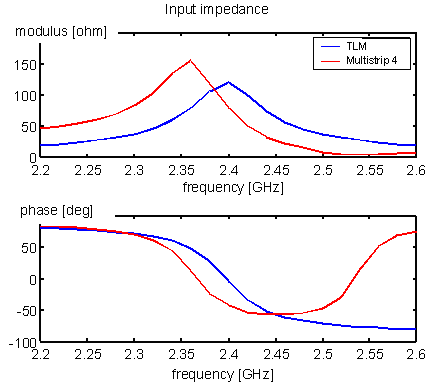
Exploiting a Matlab program (click here) for download), following results are obtained:
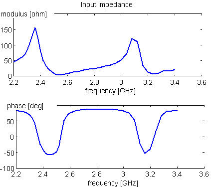
Input impedance, which is produced by the program Multistrip, is depicted by red color in the Figure as a reference. The real resonant frequency is shifted for 2% with respect to the desired one. Magnitude of the resonant resistance is for 25% lower than the desired one. The computed frequency course is not valid for higher frequencies because the simple transmission line model models the basic resonance and its multiples only. In order to demonstrate the behavior of the antenna element, input impedance is depicted for wider frequency range in the next Figure. Next parallel resonance can be observed on the frequency 3.1 GHz, which corresponds to the double length of the antenna element 2W being equal to the wavelength in dielectrics. On the antenna, a vertical current mode is excited.
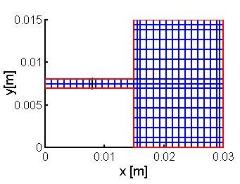
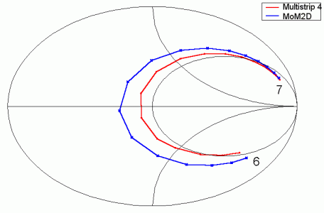
II. Analysis of standalone antenna element by moment method This paragraph is aimed to the comparison of results provided by moment method (collocation) and reference results. As a reference, the program Multistrip is used. As testing example, the rectangular antenna element 1.5 × 1.5 mm was used. The mesh of charge cells and comparison of computed reflection coefficient s11 with reference one are given in the following Figure. Accuracy of computing the resonant resistance is about 25% due to the approximate model of dielectrics and utilization of the collocation method. Further refinement of the mesh does not cause any increase of accuracy.
|


