4.6 Multi-band patch antennasBasic theoryIntroductionTelecommunication technology is one of technical fields with great interest in military, professional and also civil sphere. Due to commercial exploitation of complex electrical devices (e.g. mobile phones), new requirements on their properties appear all the time. Engineers are compelled to develop novel solutions they match the increasing demands on both their technical parameters and physical dimensions. Miniature antennas of modern communication devices have to be able to receive and transmit electromagnetic waves in different frequency bands related to different communication services. The characteristics and analysis of single-band patch antenna was discussed in the previous chapter of the textbook. Now we turn our attention to patch antennas with multi-band properties. First, basic practices for obtaining multi-band resonances of patch antennas are introduced. Second, the modal analysis in the design of planar antennas is discussed. In layer B, example of a simple dual-band patch antenna and its computational model in Ansoft HFSS and CST Microwave Studio is presented. Via this chapter, we get a short overview about multi-band patch antennas and learn about their design. Beside this, we become familiar with two well-known simulation softwares. Basic types of multi-band patch antennasThere are countless numbers of approaches how to obtain multi-band resonance of planar antennas. As example we can name the stacked patch configuration, patches with slots and cuts of different shapes, antennas with shorting pins or PIFAs (planar inverted-F antennas). The mentioned types of antennas are depicted in fig. 4.6A.1. Considering the polarization, multi-band antennas can have parallel or orthogonal polarization in working frequency ranges. The orthogonal polarization is preferred in systems with polarization diversity.
Let us now describe the working principle of antennas from fig. 4.6A.1. In the case of stacked patch, the lower metallic patch is fed directly via connector (obviously coaxial probe) and the upper metallic patch is in parasitic coupling with the lower one. The configuration has two resonant frequencies – the lower one is given by the dimensions of the lower (larger) metallic patch and the higher one is given by the dimensions of the upper (smaller) metallic patch. The basic operating mode of rectangular patch is TM10. The current distribution on rectangular patch can be influenced using slots and cuts of different shapes. As a result we obtain different antenna modes at the resonant frequencies. In the case of the structure in fig. 4.6A.1b beside of the basic TM10 mode appears another resonant mode TMx0 (1 < x < 2) which radiation efficiency is the highest for band angle from 15 deg to 30 deg. The ratio of patch resonant frequencies f1/f2 extends from 1.29 to 1.60. In the case of antenna with shorting pin good impedance matching can be obtained for the first two modes positioned along the resonant length of the antenna. If the shorting pin is placed in the centre of the patch, the resonant frequency f1 of the basic TM10 mode remains not affected, whereas a new resonance emerges at the frequency f2 = 0.5 f1. That means such an antenna can works as half-wave and quarter-wave at the same time. Changing the position of the shorting pin, the ratio f1/f2 changes in interval of <2.0; 3.6> PIFAs are widely used multi-band antennas mounted in a broad range of communication devices. Space between the ground plane and the patch is filed with dielectric. As in the previous case, good impedance matching in the required frequency bands is achieved using shorting pins and also cuts and slots (at different frequencies different portions of the patch are in resonance). PIFAs can be used also for three- and four-band applications, but the design of such antennas is rather than complicated.
Detailed description of the above-mentioned antennas and other variants can be found in the literature [33], [34]. To get fundamental physical insight into the working principle of multi-band planar antennas, the basics of the modal analysis is discussed in the next section. The modal analysis describes the field distribution of particular antenna modes. It simplifies the design process and final tuning because we are able to do a good estimation about the shape and dimensions of the metallic patch to achieve resonances at required frequencies. Modal analysisIn the case of the modal analysis the planar antenna is modeled as a resonant cavity with perfect electric walls at the top and bottom. The main restriction is that the thickness of the dielectric substrate must be much smaller than the wavelength. Due to this, the variance of the electric field in the plane perpendicular to the patch (axis z) is negligible. Because of the applied boundary conditions the electric field is non-zero only along the axis z, whereas the magnetic field has non-zero components only in the x-y plane. Along the boundaries of the metallic patch the Neumann condition for electric field is valid. It expresses the fact that the derivative of the electric field intensity vector normal to the perfect magnetic conductor has to be zero (∂E/∂n = 0). It implies the boundaries of the patch can be considered as perfect magnetic conductor. The component of the electric field intensity perpendicular to the plane of the patch satisfies the scalar wave equation
The magnetic field vector H which is proportional to the current density J on the patch surface, can expressed as the gradient of the electric field intensity Ez using the equation
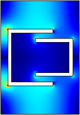
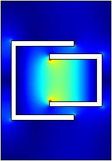
To solve the wave equation (4.6A.1), the finite element method software Comsol Multiphysics can be exploited. The patch is modeled as homogenous dielectric waveguide with the permittivity the same as the permittivity of the antenna substrate. The boundaries of the waveguide are considered to be perfect magnetic conductor. The cutoff frequencies of the computed transverse magnetic modes correspond to the antenna resonance frequencies (note that for this case it is necessary to set the value of the propagation constant near to zero, for example 0.001 rad.m-1). In fig. 4.6A.2 amplitude of the magnetic field intensity for a dual-band planar antenna with rectangular patch and double-U slot is depicted. The antenna is designed for frequency bands 2.45 GHz and 3.60 GHz. The working principle is as follows: at lower frequency resonates the whole patch, whereas at higher frequency only the smaller inner portion. In tab. 4.6A.1 the calculated resonant frequencies are summarized. Clearly, the third and fifth resonant frequencies are very close to the required ones. Parameters of the designed antenna are introduced in layer B together with the simulation results from Ansoft HFSS and CST Microwave Studio.
Using the above described modal analysis, basic characteristics of the designed antenna as resonator can be obtained in a very short time. That is because in Comsol Multiphysics we draw the longitudinally homogenous waveguide (i.e. our antenna) as a two-dimensional structure. This fact significantly reduces the computational time in comparison to three-dimensional model. | ||||||||||||||||||||||||||||||||||||||||||


