4.7 Planar ultra wideband antennasBasic theoryUltra wide band technologySystems with extreme bandwidth are one of the prospective systems of modern high-capacity radio communications. Originally, this technology has been designed for radar sensing. Due to the wide frequency band radar had the opportunity to "see" beyond barriers such as wooded sections, etc. For their resistance to interference, security against eavesdropping and small power intensity began to be used for data transmission. Today, a wide range of applications from the replacement of cables between multimedia devices such as camcorders, digital cameras and portable MP3 player through the networking of computers and peripherals, high-speed wireless universal serial bus (WUSB) to replace the cables in the third generation mobile phones. With the use of UWB technology are calculated primarily for very fast networks with short range (10m), where the need for large data throughput. Speed data transmission in broadband technology can deliver hundreds of Mb/s. Another advantage of UWB technology is the absence of the intermediate frequency modulator and demodulator and low power levels, which allows coexistence with other technologies in the same frequency band. With low power level is reduced to detection of these signals, allowing widespread use in military applications, high security transmission, and interception virtually impossible confidentiality presence of wireless devices. With regard to the bandwidth UWB (Ultra Wide Band) technology will interfere in the frequency bands other systems and it is necessary to define the spectral mask of UWB and to minimize interference with other systems. UWB technology often uses frequencies from 3.1 GHz to 10.6 GHz. This is the largest contiguous region with the highest power allowed in the defined spectral mask for UWB designated by the FCC (Federal Communications Commission). Each radio channel can have bandwidth more than 500 MHz, depending on its center frequency. Effective use of occupied frequency spectrum ensures the method of the overlay model or implementation of the ad hoc network access between nodes WPAN. Regulation of the frequency spectrum UWB due to the use the same spectrum of other radio services is not yet fully solved and in this dealt the standardizing group of IEEE 802.15.3 and IEEE 802.15.4 [40]. As already mentioned above, for this technology is characterized by a large bandwidth. In absolute terms we are talking about a minimum width of 500 MHz, in relative terms, the minimum width is 20% [39]:
where Bf is bandwidth for the observed decrease in quantity of 10dB and fc is central frequency of the bandwidth. Unlike other advanced radio technologies, broadband technologies are not harmonic and carrier information is encoded in a sequence of very short pulses (0.2 to 1.5 ns) [43]. Gaussian and Hermitian pulses are particularly used. Gaussian pulse is described by the relation [39]
In relation (4.7A.2) K3 denotes amplitude constant and τ is constant for changing pulse width. The sequence of pulses, which is encoded, usually modulates on the carrier. The most commonly used modulation is PPM (Pulse Position Modulation), PAM (Pulse Amplitude Modulation), two-phase modulation, amplitude keying modulation and orthogonal [39]. This type of modulation practically eliminates distortion reflection, respectively, and multipath receiving. Planar ultra wideband antennasPlanar antennas have significant advantages (small size, low profile and easy integrability into planar microwave circuits, low manufacturing cost in serial manufacturing), but when used in UWB applications, it is necessary to solve their shortcomings, which include mainly narrow impedance bandwidth, low polarization purity, low radiation efficiency. Increase bandwidth can be achieved by many different techniques, as will be shown below. The main feature of broadband antennas is the minimal variation of the electrical parameters in a relatively wide frequency band. When designing an antenna, the emphasis is put on the stability of input impedance (the standing wave ratio should not exceed 2). Antenna characteristics depend on the relative dimensions of the antenna to the wavelength. Theoretically, if the length of the antenna is infinite, then the antenna bandwidth can be infinite too. Since the implementation of such antennas is not possible, it is necessary to find another solution. The most commonly used types of planar antennas for UWB technology:
The definition of bandwidth for UWB planar antenna:
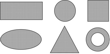
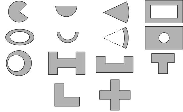
Generally, the bandwidth of microstrip antennas depends on the shape of emitters (patch), on the properties of the substrate, on the feed type, on the value of quality factor of the antenna, on the excited multiple resonance and on the impedance matching. This is valid for broadband planar antennas also. Furthermore, the effects of the basic parameters of the planar antennas on the broadband behavior will be given. Shape of the patchA metallic patch of a given shape is etched on a dielectric substrate. A metallic layer should be well-conductive. Patch length is equal to half the wavelength on the substrate. Patch shape affects the distribution of current on the antenna and thus the radiation characteristics of antennas. Basic shapes of the patch antennas are shown in fig. 4.7A.3a, the other used shapes of the patch antennas are shown in fig. 4.7A.3b.
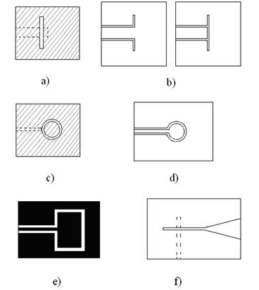
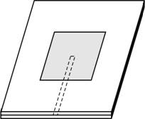
Dielectric substrateDielectric substrate used for microwave antennas is often of a relative permittivity of 2.2 ≤ εr ≤ 16 and loss factor 0.0001 ≤ tg δ ≤ 0.06. High permittivity εr has usually the effect of reducing the radiation efficiency of the antenna. Thickness of the substrate is much smaller than the wavelength. FeedingFeeding structure affects the impedance matching, operating modes, parasitic radiation, the radiation of surface waves, and radiated power. The most commonly used feeding is coaxial probe (outer conductor is connected to ground plane, an internal wire is connected with antenna element) and microstrip feeding (fig. 4.7A.4).
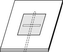
In some applications, galvanic-separated coupling is used: an antenna is excited by field of the microstrip line (fig. 4.7A.5a) or through the slot (fig. 4.7A.5b) by the so-called aperture coupling.
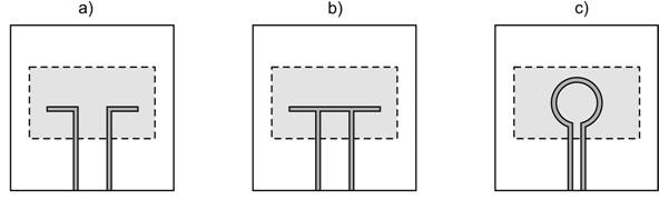
By requirements for high bandwidth, the antennas are often coupled with coplanar feeding (fig. 4.7A.6). Connection between patch and CPW can be inductive (fig. 4.7A.6a) or capacitive one (fig. 4.7A.6b). Backward radiation can be reduced by substitution of long direct slot over a circular loop (fig. 4.7A.6c), the loop is located under the center of the patch [39].
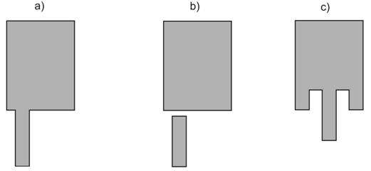
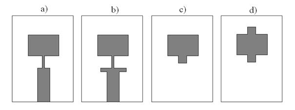
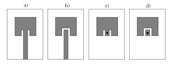
Decreasing of the quality coefficientThe broadband planar antennas can be considered as a circuit of a high quality factor. Increasing the bandwidth, quality factor of the antenna has to be reduced. Quality factor can be reduced by selecting appropriate patch shape (this affects operating modes, and thus radiation efficiency of antennas [41]), and a suitable choice of dielectric substrate (thick substrate with low relative permittivity extending the bandwidth). Impedance matchingFeeder exhibits frequency-stable characteristic impedance; the input impedance of the antenna is frequency dependent. The contradiction can be solved by the insertion of a separate adaptive circuit - quarter wave impedance transformer (fig. 4.7A.7a), tuning stubs (fig. 4.7A.7c,d), combinations of them (fig. 4.7A.7b) or adapting the patch shape by slots and notch (fig. 4.7A.8).
A well-matched antenna should cover the desired operating frequency range when keeping the defined level of the parameters which should vary marginally only (VSWR < 2, module of the reflection coefficient s11 < -10 dB, stable value of gain, the main lobe beam width and radiation pattern over the desired bandwidth). In the layer B, a concrete example of the calculation of broadband planar antennas is mentioned. We show the influence of the patch shape and his size, the choice of coupling and choice of substrate on the characteristics of the antenna. | ||||||||||||||||||||||||||||||||||||||||||||