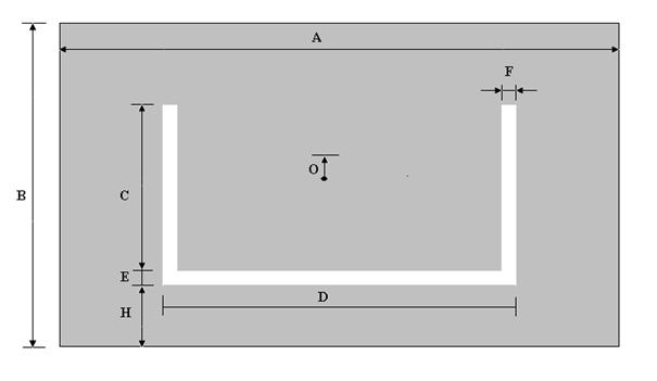
4.7 Planar ultra wideband antennasAdvanced theoryDesign of broadband planar rectangular U-slot microstrip patch antennaPlanar UWB antennas are nowadays often used in high-frequency and high-speed data communications. Planar antennas are easily positioned in small mobile devices, and easy and cheap fabrication is their great advantage. Classical patch antennas have unfortunately very narrow operating frequency band and therefore it is necessary use the techniques to increase the frequency bandwidth. One of the techniques mentioned in the layer A uses notches in the original patch shape. This method is suitable for use in antenna arrays, because they do not increase the antenna size.
Step 1:Specify the central frequency fres3 and desired frequency bandwidth (fres2 - fres4) [42]. Antenna is designed to cover both the PCS and WLAN communication from 1.8 GHz to 2.5 GHz. The central frequency is 2.15 GHz. fres2 = 1.8 GHz fres3 = 2.15 GHz fres4 = 2.5 GHz Step 2:Select a substrate permittivity (εr) and substrate thickness (T). For broadband antennas, the following rule should be satisfied:
where λres3 is wavelength in vacuum. T = 6.35 mm εr = 2.2 Step 3:Estimate the quantity (B)
B + 2ΔB ≈ 47.04 Step 4:Calculate of the width of the patch (A)
A = 70.56 mm Step 5:Calculate of the effective permitivity (εeff) and parameter 2ΔB
εeff = 2.465 2ΔB = 6.249 Step 6:Back calculate of the length of the patch (B)
B = 38.19 mm Step 7:Select a starting value of slot thickness (E, F)
E = F = 2.33 mm Step 8:Calculate width of the U-slot (D)
D = 21.93 mm Step 9:Select C such that
, Step 10:Calculate the effective permittivity and effective length extension of the pseudo-patch of the fourth resonance with effective patch width as D-2F
εeff(PP) = 2.996 2ΔB-E-H = 5.32 Step 11:Estimate of the position U-slot
For C = 23.28 H ≈ 11.41 Step 12:Check that sum C + E + H is less than B. If not adjust C by changing the rations in step 9 and value of H until the design is physically realizable.
|
