Chapter 7: Radio opticsIntroductionThe term electric signal usually denotes a time-variant voltage U(t), current I(t) or electric field intensity E(t). Time dependency of those quantities contains an information. Every electric signal can be composed of a finite or infinite number of harmonic voltages (currents, intensities) of various frequencies, amplitudes and initial phases. Amplitudes and phases of those spectral components are given by the spectral function S(ω). The signal can be therefore described by the relation
In that relation, ω is angular frequency and t is time. The signal is said to be given by the addition of its spectral components or by inverse Fourier transform of its spectral function (according to eqn. (7.1)). Since a simple harmonic oscillation is the basic building stone of a signal, we consider this oscillation as elementary signal even it does not bear any information. The elementary signal is determined by its amplitude, phase and (temporal) frequency f, or time period T = 1/f. Electromagnetic wave can contain information in time dependency of electric field intensity E(t). Since the wave exists in the space, information can be hidden even in the spatial distribution of intensity. Then, we speak about optical signal. The spatial signal is richer than the electric one because it is a function of two variables (x, y). It is associated with an electromagnetic wave (with amplitude distribution of field intensity in the plane, which is perpendicular to the direction of propagation). In analogy to the elementary electric signal, elementary spatial signal can be introduced. If coordinate system x, y is given in a plane, which is perpendicular to the direction of propagation, then a pure harmonic variation of amplitude of field intensity in an axis direction is elementary optical signal. In the direction of the second axis, amplitude of field intensity is constant (independent to y). If such wave illuminates a projection screen, a set of dark and light strips of unclear transitions can be seen (the darkest strips correspond to the minimum of the harmonic function, the lightest strips to the maximum). Distance between two neighboring strips is called spatial period Tx. Reverse value of the spatial period is called spatyial frequency fx. From the mathematical point of view, elementary optical signal for x-direction can be expressed as follows:
For y-direction:
Composing these two elementary signals together, two-dimensional spatial signal is obtained:
Optical signals can be written in symbolic way. Then, we get:
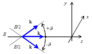
In analogy to the time domain, every spatial signal E(x, y) can be composed of elementary spatial signals of different spatial frequencies, of different amplitudes and different initial phases. Fourier transform corresponding to (7.1) is, of course, two-dimensional. Elementary spatial signal is non-uniform plane wave. Handling those waves is rather complicated, and therefore, non-uniform waves are decomposed to three uniform plane waves. In fig. 7.1, blue arrows denote directions of propagation of three paraxial waves, which amplitudes are E/2, E and E/2, and which propagate in three symmetric directions with respect to the axis z. Symbols k denote wave vectors of respective waves. Now, the resultant field distribution in the plane xy in the parallel direction to the axis y is computed. For that purpose, projections of wave vectors to the direction y have to be determined:
The computed intensity is given by the addition of three plane waves, which propagate in the direction y , and which are described by wave numbers k1y, k0y, k2y:
That way, we computed the cosine distribution of the amplitude Ey, and consequently, the elementary optical signal of the spatial frequency ωy = k.sin ϑ. Now, a general spatial signal can be decomposed by Fourier transform to elementary optical signals, and each elementary signal can be further decomposed to the triplet of uniform waves. The above-described principles form the basics of radio optics - on radio frequencies, the spatial distribution of signals is handled the same way as in optics. Considering the electromagnetic nature of the spatial signal, there is no reason to deny this approach. In the par. 7.1, we describe Gaussian beam - a narrow beam of coherent radiation. As an example of Gaussian beam, a laser beam of the basic mode TEM00 can be considered, which leaves the source with planar equiphase surface perpendicular to the direction of propagation. The beam is not intentionally modulated, but the transversal field distribution is not constant. The maximum intensity appears as the axis of the beam and the intensity decreases towards the margin of the beam following the Gaussian function. Gaussian beam is let to pass a system of spatial layers and lenses, and variation of its parameters is observed. The task is typical for optical applications, but we can meet it even on low (radio) frequencies. Par. 7.2 deals with the passage of Gaussian beam through various spatial elements (lenses, layers of media, etc.), and with the description of those phenomena by matrix notation. Gaussian beam is described by the vector of parameters, optical elements are described by matrices. Multiplying a vector of Gaussian beam parameters at the input of an optical element by the matrix of an optical element, a vector of Gaussian beam parameters at the output of an optical element is obtained. |
