7.2 Passage of Gaussian beam through optic elementsBasic theoryIn this paragraph, influence of various optical elements to the parameters of passing
Gaussian beam
is studied. If Gaussian beam propagates through a circularly symmetric system, which consists of a sequence of optical elements, then the nature of
a beam stays Gaussian, and only its parameter change. This change of parameters can be simply computed by
matrix optics.
Parameters of Gaussian beam
can be observed depending on the position of the observation point (a coordinate on the optical axis) and on the angle between the position vector of
the observation point and the optical axis. In paraxial approximation, the position and the angle are mutually associated by two algebraic equations.
The optical system is therefore described by the matrix of size 2 × 2. This matrix is called the
matrix of beam.
In general:
|
.
|
( 7.2A.1 )
|
Here, y1 is position of the input of an optical element, y2 is position of the output, θ1
is an angle at the input of the optical element, and θ2 is an angle at the output (with respect to the optical axis).
ABCD law
Let us denote parameters of
Gaussian beam
at the input plane of the optical element as q1, and parameters of Gaussian beam at the output plane of the optical element as
q2. The optical element is described by the matrix [A, B; C, D]. We can show that all the introduced
quantities are related by the equation
|
.
|
( 7.2A.2 )
|
Since parameters q determine the half-width of the Gaussian beam W and its curvature radius R, eqn.
(7.2A.2), which is called
ABCD law,
describes the transform of the
Gaussian beam
by an arbitrary paraxial optical system.
Transmission matrices of simple optical elements
In this paragraph, matrices of the most frequently used optical elements are given.
Propagation in vacuum
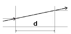 |
| Fig. 7.2A.1 | Vacuum of the length d |
|
A distance d in free space can be considered as the simplest
optical element. Since wave propagates along beams, coordinates of the beam, which passes through the distance d, change according to the equation
y2= y1 + θ1d and θ2 = θ1. The transmission matrix
M is therefore
Refraction on planar boundary
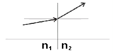 |
| Fig. 7.2A.2 | Refraction on planar boundary of two media of different refraction index |
|
On planar boundary of two media of refraction indexes
n1 and n2, angles of the beam change according to the
Snell law
|
.
|
( 7.2A.4 )
|
In paraxial approximation, we have n1θ1 ≈ n2θ2, and therefore,
position of the beam stays unchanged, i.e. y2 = y1. The transmission matrix M is therefore
|
.
|
( 7.2A.5 )
|
Refraction on spherical boundary
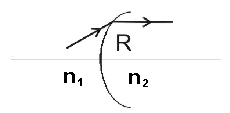 |
convex boundary: R>0
concave boundary: R<0 |
| Fig. 7.2A.3 | Refraction on spherical boundary of two media of different refraction index |
|
Relation between angles θ1 and θ2
for paraxial beams refracting on a spherical boundary of two media is given by
|
.
|
( 7.2A.6 )
|
The distance of the beam from the axis stays unchanged, i.e. y2 ≈ y1. The transmission matrix
M is therefore:
|
.
|
( 7.2A.7 )
|
Passage through a thin lens
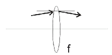 |
convex lens: f>0
concave lens: f<0 |
| Fig. 7.2A.4 | Passage through a lens of focus distance f |
|
Relation between angles θ1 and θ2
for paraxial beams, which pass through a thin lens of the focus distance f, is:
The distance form the axis stays unchanged. The transmission matrix M is therefore:
|
.
|
( 7.2A.9 )
|
Reflection from planar mirror
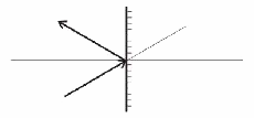 |
| Fig. 7.2A.5 | Reflection from planar mirror |
|
Reflecting beam from a planar mirror, the position of a beam stays
unchanged (y2 = y1). For angles, we get θ2 = θ1. Hence, the transmission matrix
is unitary
Reflection from spherical mirror
 |
convex mirror:
concave mirror: |
| Fig. 7.2A.6 | Reflection from spherical mirror |
|
Exploiting (7.2A.9), we obtain:
|
,
|
( 7.2A.11 )
|
|
.
|
( 7.2A.12 )
|
Transmission matrix of the sequence of optical elements
 |
| Fig. 7.2A.7 | Sequencing optical elements |
|
Sequence of optical elements, which are described by matrices
M1, M2, ..., MN, is equivalent to a single optical element of the transmission matrix:
|
.
|
( 7.2A.13 )
|
Note the order of the matrix multiplication. The matrix of the element, which is entered by the beam first, appears on the right, and therefore,
it multiplies the column vector of the incident beam first.
More information can be found in [16].
| 


