8.1 Drift diffusion modelDeveloping Comsol modelIn the following text is summarized the implementation of a model 1D silicon diodes in the program COMSOL Multiphysics in version 3.5. The basic knowledge of working with the program is assumed, so we set out
images of important dialogues that define the model. This model is a 1D structure of the doping profile of an identical as in fig. 8.1B.1. Are implemented
equation (8.1B.31) and boundary conditions for ohmic contact (8.1A.37) and (8.1A.41).
SRH recombination model and table the value of mobility carriers at 300K is used. To work with this model read the instructions in the layer C.
The diode consist of a line with the coordinates x1 = 0 and x2 = L = 8 μm. Definition of the necessary constants and expressions is given in fig. 8.1D.1, fig. 8.1D.2 and
fig. 8.1D.3.
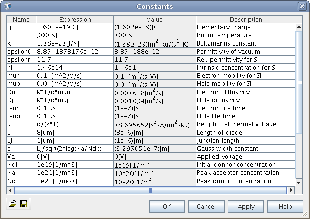 |
| Obr. 8.1D.1 | Setting of constants |
|
 |
| Obr. 8.1D.2 | Setting of expressions |
|
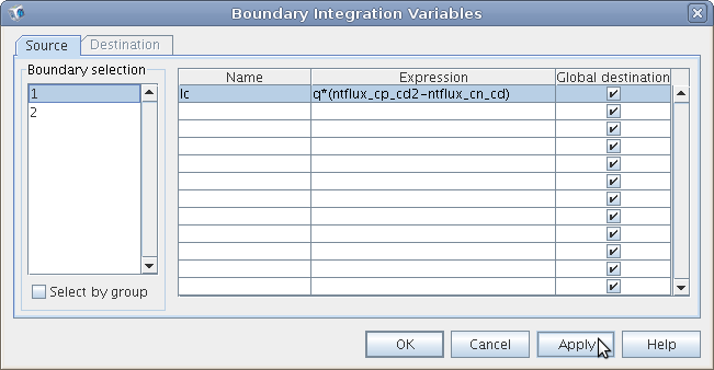 |
| Obr. 8.1D.3 | Setting of integration variables |
|
Module Poisson equation
In this section is described the electrostatic module. In fig. 8.1D.4 is depicted the settings of preset formula over the diode domain, where the tab
is set to psi_init.
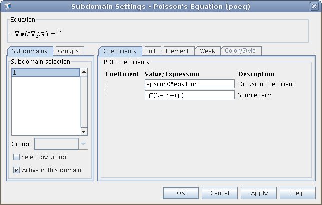 |
| Obr. 8.1D.4 | Setting of Poisson equation coefficients |
|
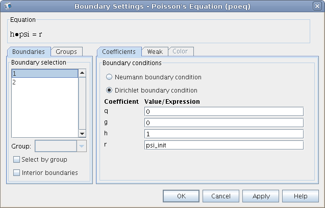
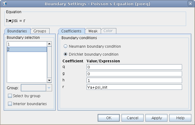
The fig. 8.1D.5 shows the set of boundary conditions at points x1 and x2.
 |
| a) |
 |
| b) |
| Obr. 8.1D.5 | Setting of boundary conditions of the electrostatic module |
|
Module convention and diffusion of electrons
In fig. 8.1D.6 is depicted the preset formula over the diode domain, where the tab is set to n_init.
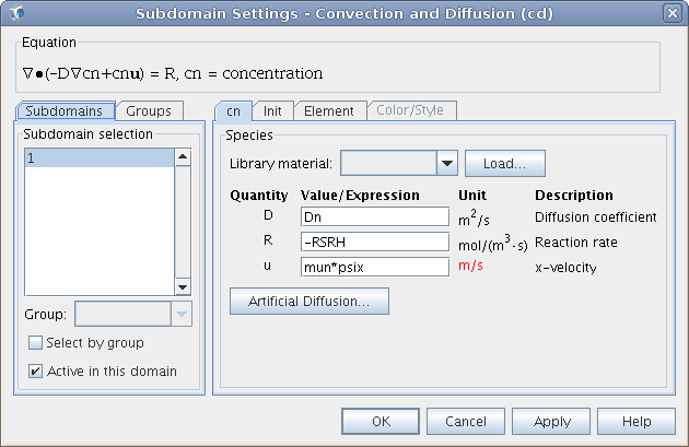 |
| Obr. 8.1D.6 | Setting of convention and diffusion equations for electrons |
|
The fig. 8.1D.7 shows identical set of boundary conditions of points x1 and x2.
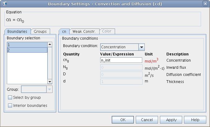 |
| Obr. 8.1D.7 | Set of boundary conditions for convention and diffusion module of electrons |
|
Module convention and diffusion of holes
In fig. 8.1D.8 is depicted the preset formula over the diode domain, where the tab is set to p_init.
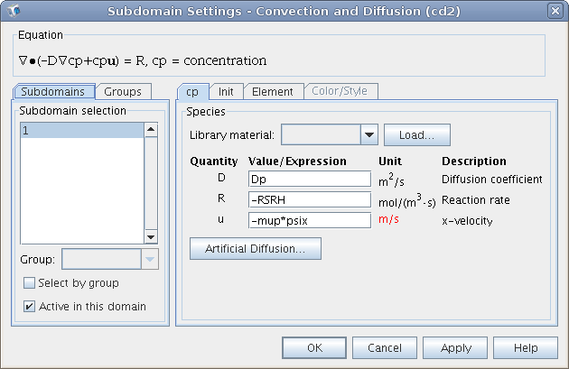 |
| Obr. 8.1D.8 | Setting of convention and diffusion equations for holes |
|
The fig. 8.1D.9 shows identical set of boundary conditions of points x1 and x2.
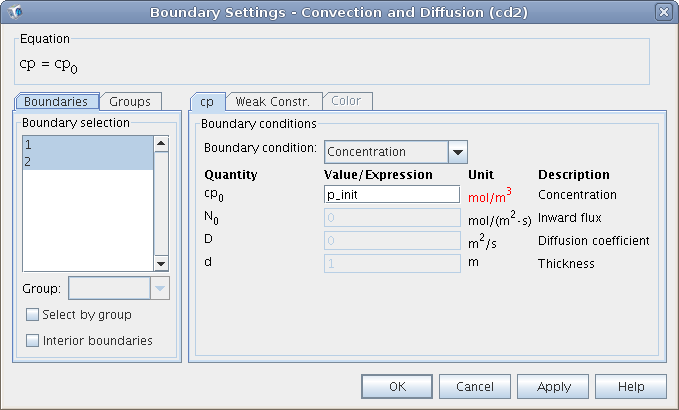 |
| Obr. 8.1D.9 | Setting of boundary conditions for convention and diffusion module of holes |
|
Other settings
Setting of discretization mesh is shown in fig. 8.1D.10 and settings of solver in fig. 8.1D.11.
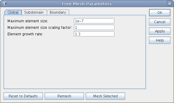 |
| Obr. 8.1D.10 | Setting of the density discretization mesh |
|
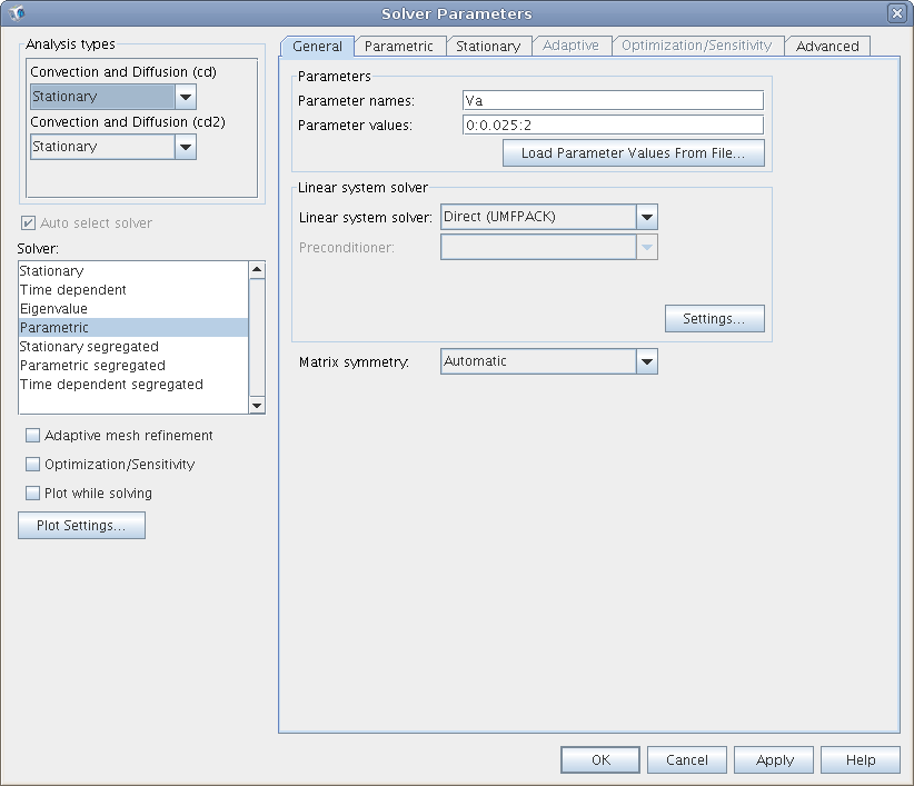 |
| Obr. 8.1D.11 | Setting of solver parameters |
|
| 


