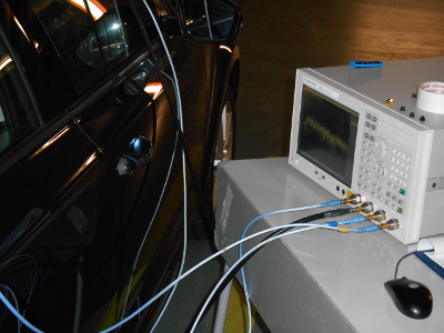
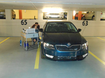
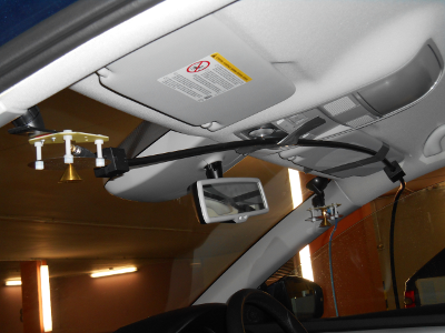
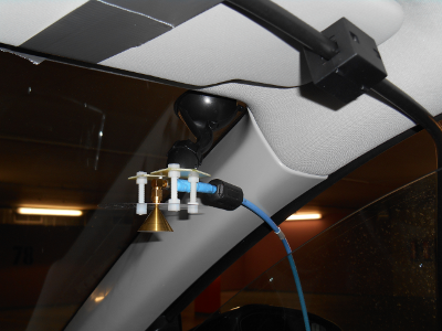
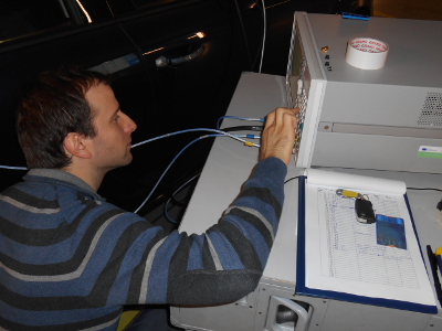
M3. UWB measurement in frequency domain using VNA E5071C and spatial grid (10 x 10 spatial positions distant 3 cm each other) for antenna positioning (May 2014). The aim of the measurement was to analyze the spatial stationarity of the intra-vehicle channel.
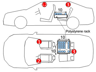
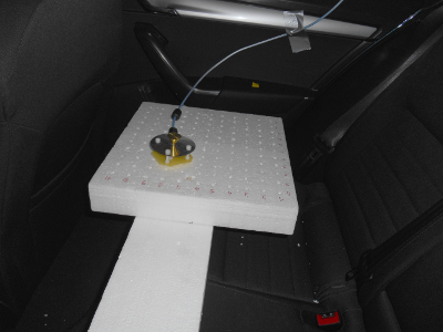
The aim of this measurement was to analyze the spatial stationarity of the intra-vehicle channel. The measurement setup was identical as in the case of measurements of UWB in-vehicle channel in frequency domain performed on 17 Oct and 7 Nov 2013. The RX antenna and TX antennas were placed according to Figure 1. The receiving antenna was placed at 10×10 spatial points using the polystyrene rack which ensured defined location of the antenna. The polystyrene rack utilizes a 3 cm grid distance between neighboring measurement locations. For details of the measurement campaign please refer to [1]
Examples of measured scenarios:
- Position on the spatial grip № 6 of Rx antenna: Download
- Position on the spatial grip № 21 of Rx antenna: Download
- Position on the spatial grip № 56 of Rx antenna: Download
- Position on the spatial grip № 63 of Rx antenna: Download
- Position on the spatial grip № 80 of Rx antenna: Download
Equipment of measuring workplace:
- Vector Network Analyzer Agilent E5071C
- Phase-stable coaxial cables SUCOFLEX 104P
- Conical monopole antennas
- 10×10 polystyrene rack with a 3 cm grid distance
- Vacuum glass holders
- SMA female to SMA male 90-deg bend adapters
- SMA female to SMA female straight adapters
 |
 |
 |
 |
|
 |
Related publications:
| [1] |
BLUMENSTEIN, J.; MIKULÁŠEK, T.; MARŠÁLEK, R.; CHANDRA, A.; PROKEŠ, A.; ZEMEN, T.; MECKLENBRÄUKER, C.
In-vehicle UWB Channel Measurement, Model and Spatial Stationarity
In 2014 IEEE Vehicular Networking Conference (VNC). 2014.
|