M1. MMW measurement in frequency domain (February 2014) based on ZVA67 and Quinstar power amplifier QPW-50662330-C1 (purchased from grant funds).
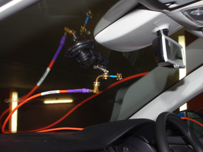
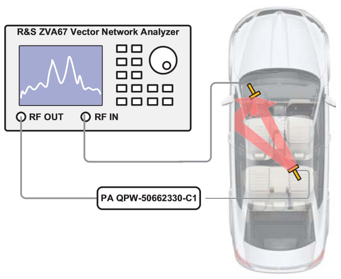
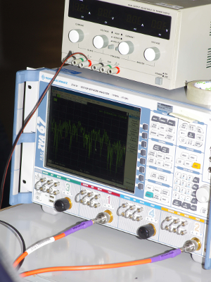
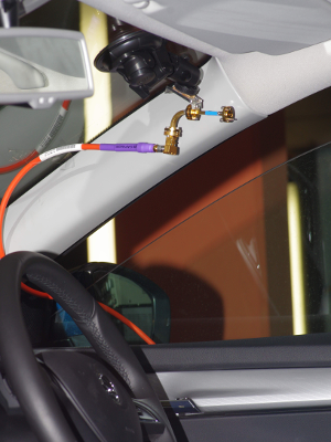
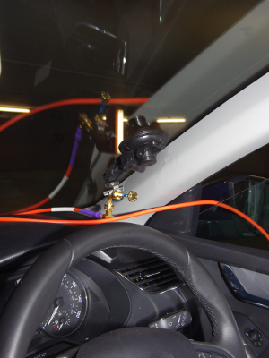
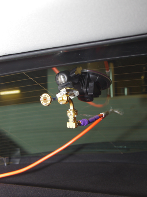
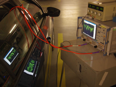
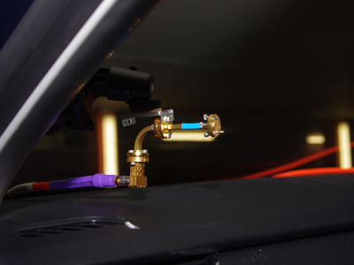
The scheme of the measurement workplace is shown in Figure 1. The transmission coefficient corresponding to the s21 scattering parameter between two antennas in the frequency band 55–65 GHz was measured utilizing a four-port vector network analyzer R&S ZVA67 (VNA). The dynamic range of the VNA was increased utilizing a broadband power amplifier on the transmitting side. The measurement was carried out in the Skoda Octavia 1.8 TSI car. In order to avoid a degradation of the measured phase accuracy due to movements of the RX a TX antenna, phase-stable coaxial cables were used and included in the calibration process. Open-ended waveguide antennas were used as a transmitting and receiving antenna. The measurement setup was calibrated for zero transmission while the open-ended waveguide antennas were connected to each other.
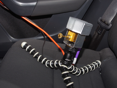
The TX antenna was placed at several locations inside the car compartment (on driver’s and passenger’s seat) and the RX antenna was placed on the left and right side of the dashboard, top corners of the windshield, and at the rear part of the ceiling. The channel measurements were carried out for both LOS and NLOS scenarios. NLOS was caused by the backrest of the seats and/or persons sitting inside the vehicle. For details of antenna placement please refer to [1].
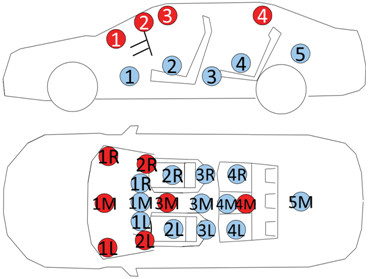
Examples of measured scenarios:
- Position № 1 of Rx antenna: Download
- Position № 5 of Rx antenna: Download
- Position № 21 of Rx antenna: Download
VNA specifications for MMW measurement:
- Start frequency 55 GHz
- Stop frequency 65 GHz
- Bandwidth 10 GHz
- Frequency step size 10 MHz
- 1001 points
- IF bandwidth 100 Hz
- Dynamic range > 60 dB
- Output power 5 dBm
Equipment of measuring workplace:
- Vector Network Analyzer R&S ZVA67
- MMW broadband power amplifier QuinStar QPW-50662330-C1
- DC power supply M10-DP-305E
- Phase-stable coaxial cables MEGAPHASE: TM67-V1V1-98, TM67-V1V1-138
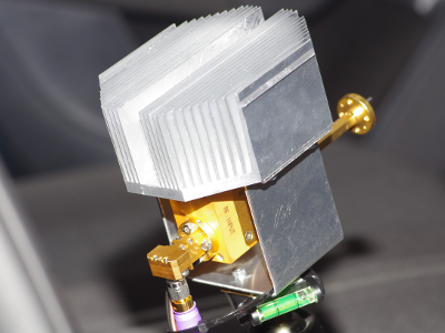
- Open-ended waveguide antennas QuinStar QWS-V02000
- Waveguide components QuinStar: QWB-V90ER, QWB-V90HR, QWT-V90RR
- WR-15 to 1.85mm female adapters QuinStar QWA-15R18F00
- 1.85 mm female to 1.85 mm female adapters
- JOBY GorillaPod
- Vacuum glass holder
 |
 |
 |
 |
 |
 |
 |
 |
Related publications:
| [1] |
BLUMENSTEIN, J., MIKULÁŠEK, T., MARŠÁLEK, R., PROKEŠ, A., ZEMEN, T., MECKLENBRÄUKER, C.
In-vehicle mm- Wave Channel Model and Measurement
In Proc. of IEEE 80th Vehicular Technology Conference (VTC Fall). Vancouver, Canada, 2014, p. 1-5, ISBN: 978-1-4799-4450-7.
|
| [2] |
BLUMENSTEIN, J.
Intra-Vehicular Path Loss Comparison of UWB Channel for 3–11 GHz and 55–65 GHz
IEEE International Conference on Ubiquitous Wireless Broadband ICUWB’2015, accepted for publication.
|