Uživatelské nástroje
Obsah
Tilt sensing with a 3-axis accelerometer
Author: Jiri Krivak
Assignment
Calculate the roll and pitch values from a 3-axis accelerometer. Use the development board STM32F4DISCOVERY with LIS302DL / LIS3DSH devices. Consider any accelerometer position relative to the base, i.e. implement the compensation by de-rotation of input data vector as described in DT0076.
Introdunction
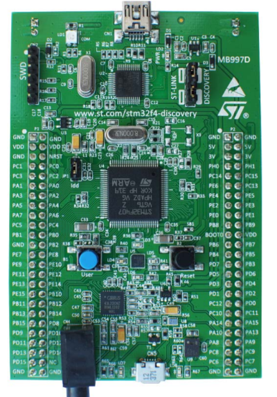
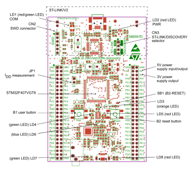
STM32F4DISCOVERY
KEY FEATURES
- STM32F407VGT6 microcontroller featuring 32-bit ARM®Cortex®-M4 with FPU core, 1-Mbyte Flash memory, 192-Kbyte RAM in an LQFP100 package
- On-board ST-LINK/V2 on STM32F4DISCOVERY
- USB ST-LINK with re-enumeration capability and three different interfaces: Debug port
- Board power supply: through USB bus or from an external 5 V supply voltage
- External application power supply: 3 V and 5 V
- LIS302DL or LIS3DSH ST MEMS 3-axis accelerometer
- MP45DT02 ST-MEMS audio sensor omnidirectional digital microphone
- CS43L22 audio DAC with integrated class D speaker driver
- USB OTG FS with micro-AB connector
- Comprehensive free software including a variety of examples, part of STM32CubeF4 package or STSW-STM32068 to use legacy standard libraries.
Implementation
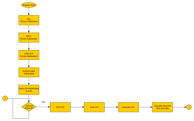
The application was created by using HAL Drivers, STM32F4-Discovery (to map PINs for Discovery), Driver for accelerometer from STMicroelectronics. Next, we use a Middleware library from STMicroelectronics to create Virtual Com Port. We also used ARM GCC Libraries: stdio.h, stdlib.h, math.h The app was designed for Em::Bitz and its integrated ARM GCC Compiler. Because we use function Printf with floats, we need to give the GCC compiler flag that tells it that floats are used for string formatting we also use mathematical library math.h, so we need to provide the linker flag to include mathematical libraries. GCC Compiler Flag: -u _printf_float Linker Flag: -lm
USB Virtual Com Port and communication
To create Virtual Com Port we used middleware libraries from STMicroelectronics. For easier communication, we remapped the Printf function so that when it is called we send data over the USB VCP. Remapping of Printf in ARM GCC is done by modification of _write function.
int _write(int fd, char * str, int len)
{
    for (int i = 0; i < len; i++)
    {

        VCP_write(&str[i],1);

    }
    return len;
}
We used Legacy Middleware library for USB so it is necessary to install VCP Driver from STMicroelectronics.
Calculation of Reference Roll, Pitch, Yaw
From XYZ values in reference possition we calculate Roll (Phi), Pitch (Theta) and Yaw (Psi)
Phi   = atan(y / sqrt( z^2 + x^2)) ;
Theta = atan( -x / sqrt(y^2 + z^2)) ;
Psi   = atan(z / sqrt(y^2+x^2) ) ;
We get the values of Phi,Theta,Psi in radians that are used for derrotation of XYZ. These values were calculated using MatLab, and the script is not implemented inside the ST32F4-Discovery boards' Firmware.
Derotation
Using the values of Roll, Pitch, Yaw we de-rotate the XYZ to Reference so we can get values relative to the Base (Reference Position). We use the method of derotation as is described in DT0076 documentation for compensation of installation error for Accelerometer. To implement this we used GCC mathematical libraries math.h
// Callibration with Reference Plane
void derotate_vector(double *Vect ,double phi,double theta,double psi , int16_t XYZ[3])
{
// Roll(phi) Pitch(theta) Yaw(psi), angles in radians
double m11 = cos(theta)*cos(psi);
double m21 = cos(theta)*sin(psi);
double m31 = -sin(theta);
double m12 = sin(phi)*sin(theta)*cos(psi)-cos(phi)*sin(psi);
double m22 = sin(phi)*sin(theta)*sin(psi)+cos(phi)*cos(psi);
double m32 = sin(phi)*cos(theta);
double m13 = cos(phi)*sin(theta)*cos(psi)+sin(phi)*sin(psi);
double m23 = cos(phi)*sin(theta)*sin(psi)-sin(phi)*cos(psi);
double m33 = cos(phi)*cos(theta);
 // derotate vector (product matrix by vector)
Vect[0] = m11*XYZ[0] + m12*XYZ[1] + m13*XYZ[2];
Vect[1] = m21*XYZ[0] + m22*XYZ[1] + m23*XYZ[2];
Vect[2] = m31*XYZ[0] + m32*XYZ[1] + m33*XYZ[3];

}
Roll Pitch Calculation
From the derotated vectros we calculate Roll and Pitch. These are then sent by USB VCP to Terrminal in computer.
//calaculation of Roll and Pitch - outputn in angles
void PITCH_ROLL(double InputData[3])
{

  double x_Buff = InputData[0] ;
  double  y_Buff = InputData[1] ;
  double  z_Buff = InputData[2] ;
  printf("ROT: X axis: %lf Y axis: %lf Z axis: %lf \r",x_Buff,y_Buff,z_Buff);
  double pitch = atan(y_Buff / sqrt( z_Buff * z_Buff + x_Buff * x_Buff)) * 57.3;
  double roll  = atan((- x_Buff) / sqrt(y_Buff * y_Buff + z_Buff * z_Buff)) * 57.3 ;
  printf("Roll: %lf Pitch: %lf\n\r",roll,pitch);

}
Source Code
VCP Driver
Summary
The board senses active Roll and Pitch related to the reference plane which is parrarel to the ground plane.
Problem with unstable reference plane
In the implementation, there was a problem that when the reference plane lies parallel to the ground, there are unstable values of the XYZ values from the accelerometer. This results in instability of reference plane. One possible solution for this is to use a different reference plane.
Video
— Jiří Křivák 2019/05/01 21:46
References and Sources
- http://www.embitz.org/ - Ide Used


